
Wi-Fi Enabled Gas Leak Detector with Buzzer Alert using MQ-2 and ESP8266
View and Edit Project In Cirkit Designer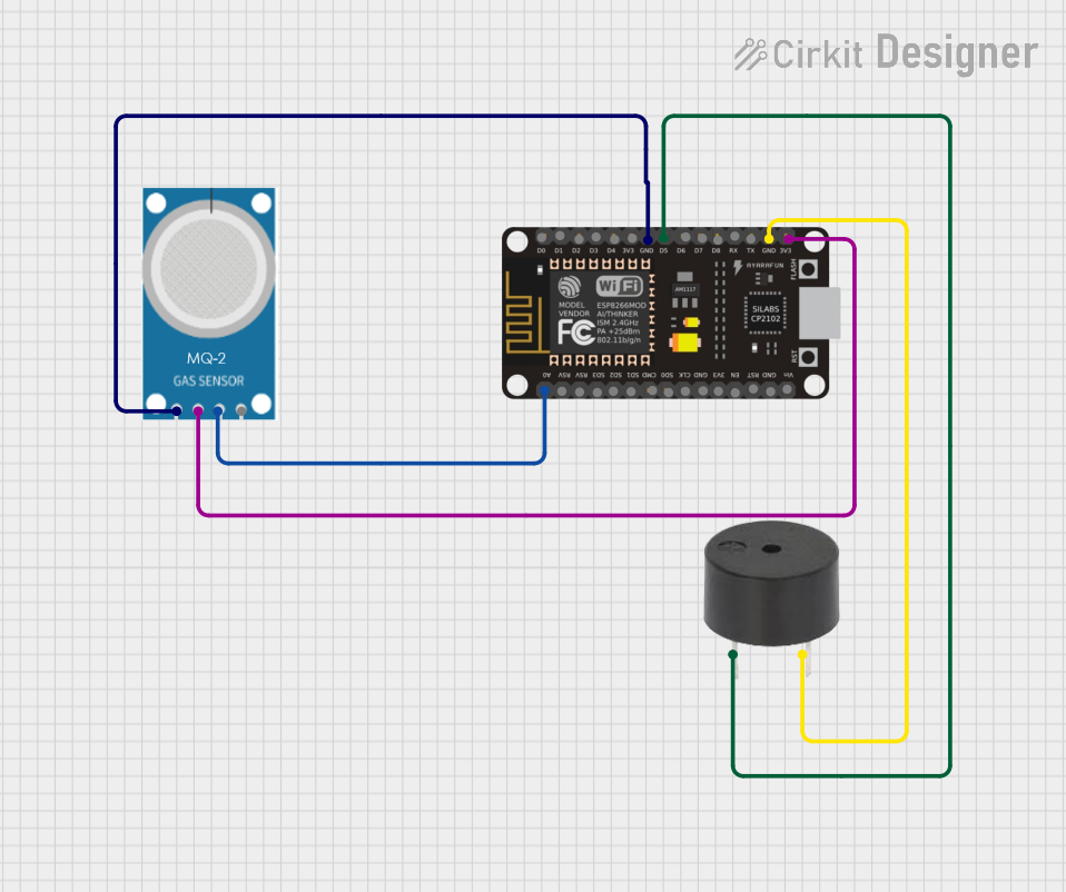
Circuit Documentation
Summary
This document provides a detailed overview of a circuit that includes an MQ-2 gas sensor, an ESP8266 NodeMCU microcontroller, and a buzzer. The circuit is designed to detect gas levels using the MQ-2 sensor and trigger the buzzer through the ESP8266 NodeMCU when certain conditions are met.
Component List
MQ-2 Gas Sensor
- Description: A gas sensor used to detect various gases including LPG, i-butane, propane, methane, alcohol, Hydrogen, and smoke.
- Pins: GND, VCC, ANALOG, Digital
ESP8266 NodeMCU
- Description: A low-cost Wi-Fi microcontroller with GPIO, ADC, and other functionalities.
- Pins: D0, D1, D2, D3, D4, 3V3, GND, D5, D6, D7, D8, RX, TX, A0, RSV, SD3, SD2, SD1, CMD, SD0, CLK, EN, RST, VIN
Buzzer
- Description: An audio signaling device, typically used to alert or signal.
- Pins: PIN, GND
Wiring Details
MQ-2 Gas Sensor
- GND is connected to GND of the ESP8266 NodeMCU.
- VCC is connected to 3V3 of the ESP8266 NodeMCU.
- ANALOG is connected to A0 of the ESP8266 NodeMCU.
ESP8266 NodeMCU
- GND is connected to GND of the MQ-2 Gas Sensor.
- 3V3 is connected to VCC of the MQ-2 Gas Sensor.
- A0 is connected to ANALOG of the MQ-2 Gas Sensor.
- D5 is connected to PIN of the Buzzer.
- GND is connected to GND of the Buzzer.
Buzzer
- PIN is connected to D5 of the ESP8266 NodeMCU.
- GND is connected to GND of the ESP8266 NodeMCU.
Code
No code is provided for this circuit.
This documentation provides a comprehensive overview of the components and their interconnections in the circuit. The wiring details ensure that each component is correctly connected to the ESP8266 NodeMCU, enabling the circuit to function as intended.