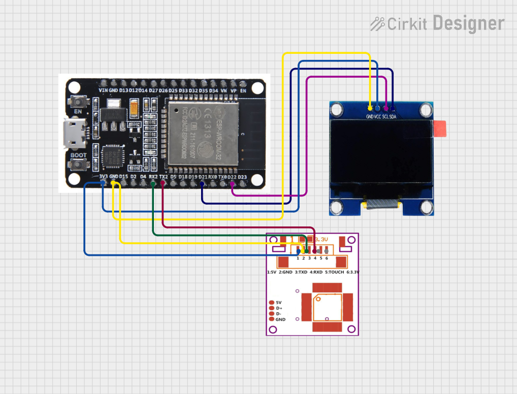
ESP32-Based Fingerprint Authentication System with OLED Display

Circuit Documentation
Summary
The circuit in question is designed to interface an ESP32 microcontroller with an R307 Fingerprint Sensor and an OLED 1.3" display. The ESP32 serves as the central processing unit, managing data communication between the fingerprint sensor and the display. The fingerprint sensor is used for biometric identification, and the OLED display provides a visual interface for outputting information or status messages.
Component List
ESP32
- Description: A microcontroller with Wi-Fi and Bluetooth capabilities, suitable for a wide range of IoT applications.
- Pins: EN, VP, VN, D34, D35, D32, D33, D25, D26, D27, D14, D12, D13, GND, VIN, 3V3, D15, D2, D4, RX2, TX2, D5, D18, D19, D21, RX0, TX0, D22, D23, BOOT
R307 Fingerprint Sensor
- Description: A fingerprint sensor module capable of storing and comparing fingerprints for authentication purposes.
- Pins: VCC, GND, TX, RX, Touch, 3.3V
OLED 1.3"
- Description: A small OLED display that can be used to show text, graphics, and images.
- Pins: GND, VCC, SCL, SDA
Wiring Details
ESP32
- 3V3: Connected to the VCC of the R307 Fingerprint Sensor and the VCC of the OLED 1.3" display to provide power.
- GND: Connected to the GND of the R307 Fingerprint Sensor and the GND of the OLED 1.3" display to complete the power circuit.
- RX2: Connected to the TX of the R307 Fingerprint Sensor for serial communication.
- TX2: Connected to the RX of the R307 Fingerprint Sensor for serial communication.
- D21 (SDA): Connected to the SDA of the OLED 1.3" display for I2C data communication.
- D22 (SCL): Connected to the SCL of the OLED 1.3" display for I2C clock signal.
R307 Fingerprint Sensor
- VCC: Powered by the 3V3 output from the ESP32.
- GND: Connected to the GND of the ESP32.
- TX: Connected to the RX2 of the ESP32 for serial communication.
- RX: Connected to the TX2 of the ESP32 for serial communication.
OLED 1.3"
- VCC: Powered by the 3V3 output from the ESP32.
- GND: Connected to the GND of the ESP32.
- SCL: Connected to the D22 of the ESP32 for I2C clock signal.
- SDA: Connected to the D21 of the ESP32 for I2C data communication.
Documented Code
No code has been provided for the microcontrollers in the circuit. To fully utilize the components, embedded code for the ESP32 should be written to handle the following tasks:
- Initialize and manage I2C communication with the OLED display.
- Initialize and manage serial communication with the R307 Fingerprint Sensor.
- Implement logic for fingerprint data acquisition and processing.
- Display relevant information or status messages on the OLED display.
The code should be structured to include setup and loop functions, with appropriate initialization of serial and I2C interfaces, and error handling for robust operation.