
Raspberry Pi 4B-Based Smart Security System with Fingerprint and Keypad Access Control
View and Edit Project In Cirkit Designer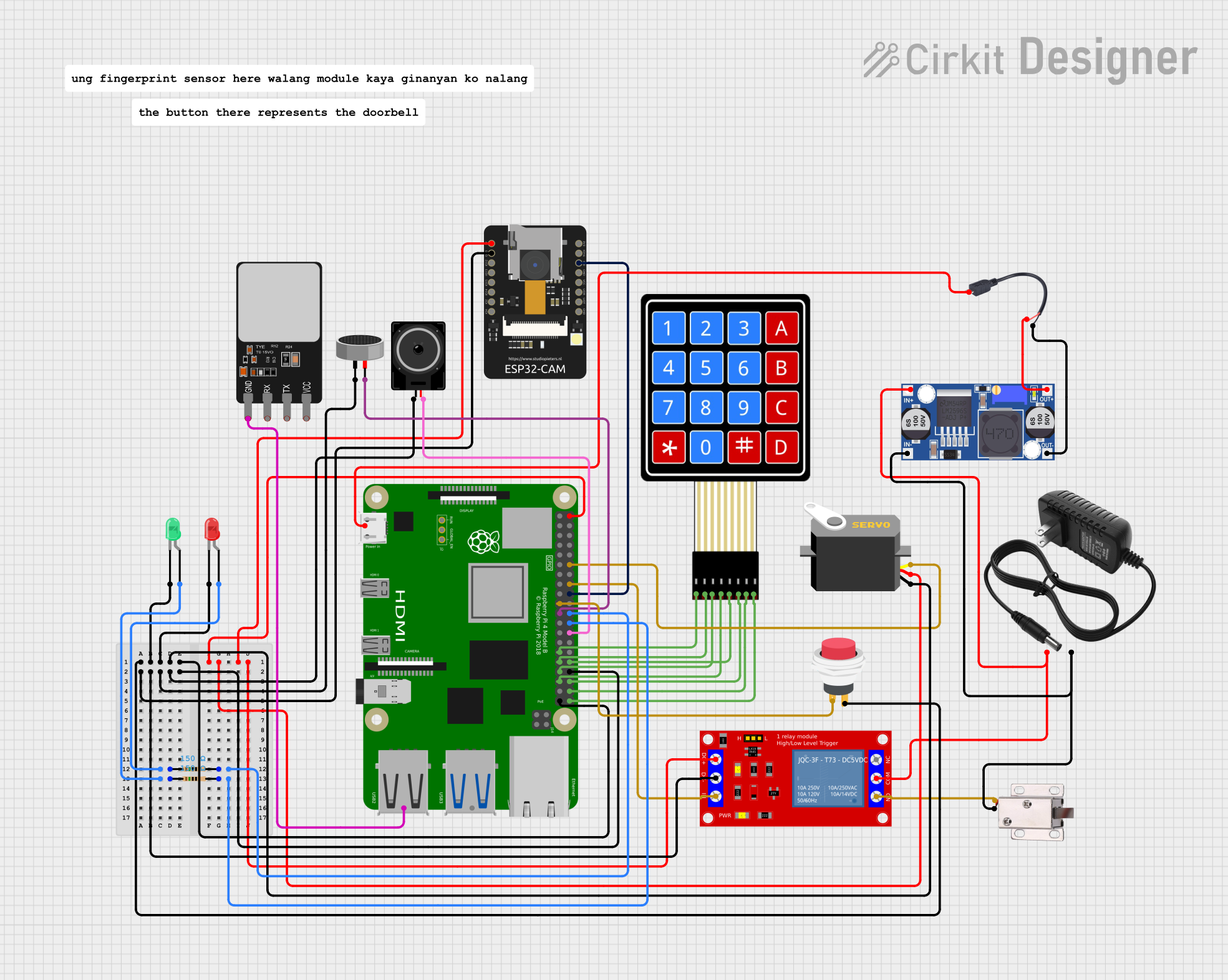
Circuit Documentation
Summary
This circuit is designed to interface with a Raspberry Pi 4B and includes various components such as a membrane matrix keypad, servo motor, relay module, power supply, ESP32-CAM, fingerprint scanner, LEDs, loudspeaker, microphone, push switch, solenoid lock, buck converter, and resistors. The circuit appears to be part of a security or access control system, utilizing a Raspberry Pi 4B as the central processing unit. The system features methods for user interaction and feedback, including a keypad, fingerprint scanner, visual indicators (LEDs), and audio output (loudspeaker). The Raspberry Pi controls a servo motor and a solenoid lock through a relay, likely for physical access control.
Component List
- Raspberry Pi 4B: A single-board computer with multiple GPIO pins used for interfacing with various components.
- 4X4 Membrane Matrix Keypad: An input device with 16 keys arranged in a 4x4 matrix, used for entering codes or commands.
- Servo: An actuator that can be precisely controlled to move to different positions.
- 1 Channel 5V Relay Module: An electrically operated switch that allows the Raspberry Pi to control higher power devices like the solenoid lock.
- 12V Power Supply: Provides power to the circuit components that require 12V.
- ESP32-CAM: A small camera module with Wi-Fi capabilities.
- Fingerprint Scanner: A biometric sensor used for identifying individuals based on their fingerprints.
- LED (Red and Green): Visual indicators for status or feedback.
- Loudspeaker: An audio output device used for sound notifications or alerts.
- Condenser Microphone: An input device for capturing sound.
- 2Pin Push Switch: A simple switch that can be used to trigger events or actions.
- 12V Solenoid Lock: An electromechanical lock that can be controlled electronically.
- Buck Converter: A DC-DC converter used to step down voltage from a higher level to a lower level.
- Micro USB to Cable (2 Pin): Used to provide power to the Raspberry Pi via a micro USB connection.
- Resistors (150 Ohms): Used to limit current to the LEDs.
Wiring Details
Raspberry Pi 4B
- 5V: Connected to the Servo (VCC), ESP32-CAM (5V), and Relay Module (VCC+).
- GND: Common ground for the Servo, LEDs, Push Switch, Loudspeaker, Microphone, and ESP32-CAM.
- GPIO Pins: Connected to various components for control signals.
- GPIO25: Connected to the Green LED (via a 150 Ohm resistor).
- GPIO8: Connected to the Red LED (via a 150 Ohm resistor).
- GPIO18: Connected to the Servo (pulse).
- GPIO23: Connected to the Relay Module (IN).
- GPIO24: Connected to the ESP32-CAM (IO0).
- GPIO10: Connected to the Push Switch (Input +).
- GPIO9: Connected to the Microphone (pin2).
- GPIO7: Connected to the Loudspeaker (pin2).
- GPIO5, GPIO6, GPIO12, GPIO13, GPIO16, GPIO19, GPIO20, GPIO21: Connected to the Membrane Matrix Keypad.
4X4 Membrane Matrix Keypad
- Rows (R1, R2, R3, R4): Connected to Raspberry Pi GPIO pins (GPIO5, GPIO6, GPIO13, GPIO19).
- Columns (C1, C2, C3, C4): Connected to Raspberry Pi GPIO pins (GPIO12, GPIO16, GPIO20, GPIO21).
Servo
- VCC: Connected to the Raspberry Pi 5V.
- GND: Common ground with Raspberry Pi.
- Pulse: Controlled by Raspberry Pi GPIO18.
1 Channel 5V Relay Module
- VCC+: Powered by Raspberry Pi 5V.
- VCC- (GND): Common ground with Raspberry Pi.
- IN: Controlled by Raspberry Pi GPIO23.
- N.O.: Connected to the 12V Solenoid Lock (VCC).
- COM: Connected to the 12V Power Supply (+) and Buck Converter (IN+).
12V Power Supply
- +: Connected to the Relay Module (COM) and Buck Converter (IN+).
- -: Common ground with the Solenoid Lock (GND) and Buck Converter (IN-).
ESP32-CAM
- 5V: Powered by Raspberry Pi 5V.
- GND: Common ground with Raspberry Pi.
- IO0: Controlled by Raspberry Pi GPIO24.
Fingerprint Scanner
- GND: Common ground with Raspberry Pi.
LED: Two Pin (Red and Green)
- Cathode: Common ground with Raspberry Pi.
- Anode (Red LED): Connected to Raspberry Pi GPIO8 via a 150 Ohm resistor.
- Anode (Green LED): Connected to Raspberry Pi GPIO25 via a 150 Ohm resistor.
Loudspeaker
- Pin1: Common ground with Raspberry Pi.
- Pin2: Controlled by Raspberry Pi GPIO7.
Condenser Microphone
- Pin1: Common ground with Raspberry Pi.
- Pin2: Controlled by Raspberry Pi GPIO9.
2Pin Push Switch
- Input +: Controlled by Raspberry Pi GPIO10.
- Output +: Common ground with Raspberry Pi.
12V Solenoid Lock
- VCC: Controlled by Relay Module (N.O.).
- GND: Common ground with 12V Power Supply (-).
Buck Converter
- IN+: Connected to the 12V Power Supply (+).
- IN-: Common ground with 12V Power Supply (-).
- OUT+: Connected to the Micro USB to Cable (2 Pin) (+).
- OUT-: Connected to the Micro USB to Cable (2 Pin) (-).
Micro USB to Cable (2 Pin)
- Micro USB: Powers the Raspberry Pi.
- +: Connected to the Buck Converter (OUT+).
- -: Connected to the Buck Converter (OUT-).
Documented Code
import RPi.GPIO as GPIO
import time
from pyfingerprint.pyfingerprint import PyFingerprint
from picamera import PiCamera
import os
import serial

# GPIO setup
GPIO.setmode(GPIO.BCM)
GPIO.setwarnings(False)

# Define pin numbers for components
green_led = 25
red_led = 8
servo_pin = 18
relay_pin = 23
doorbell_pin = 10
buzzer_pin = 7
keypad_rows = [5, 6, 13, 19]
keypad_cols = [12, 16, 20, 21]

# Set up GPIO pins
GPIO.setup(green_led, GPIO.OUT)
GPIO.setup(red_led, GPIO.OUT)
GPIO.setup(servo_pin, GPIO.OUT)
GPIO.setup(relay_pin, GPIO.OUT)
GPIO.setup(doorbell_pin, GPIO.IN, pull_up_down=GPIO.PUD_UP)
GPIO.setup(buzzer_pin, GPIO.OUT)

# Servo setup
servo = GPIO.PWM(servo_pin, 50)  # 50Hz frequency
servo.start(0)

# Set up the fingerprint sensor (modify serial port as needed)
fingerprint_sensor = PyFingerprint('/dev/ttyUSB0', 57600)

# Initialize camera
camera = PiCamera()
camera.rotation = 180

# Keypad matrix setup
keypad = [
    ['1', '2', '3', 'A'],
    ['4', '5', '6', 'B'],
    ['7', '8', '9', 'C'],
    ['*', '0', '#', 'D']
]

# Function to read keypad input (you will need to complete this for your keypad)
def get_key():
    # Placeholder for reading key from keypad
    pass

def authenticate_keypad():
    attempts = 3
    correct_code = "1234"
    while attempts > 0:
        entered_code = ""
        for _ in range(4):  # Assume 4-digit code
            entered_code += get_key()
        if entered_code == correct_code:
            unlock_door()
            return True
        attempts -= 1
        time.sleep(1)
    lock_down()
    return False

def authenticate_fingerprint():
    attempts = 3
    while attempts > 0:
        try:
            print("Waiting for fingerprint...")
            if fingerprint_sensor.readImage():
                fingerprint_sensor.convertImage(0x01)
                result = fingerprint_sensor.searchTemplate()
                position_number = result[0]
                if position_number >= 0:
                    unlock_door()
                    return True
                else:
                    print("Fingerprint not recognized.")
            attempts -= 1
        except Exception as e:
            print("Error reading fingerprint: ", str(e))
    lock_down()
    return False

def unlock_door():
    GPIO.output(green_led, GPIO.HIGH)
    GPIO.output(relay_pin, GPIO.HIGH)
    play_tune(success=True)
    time.sleep(5)  # Keep the door unlocked for 5 seconds
    GPIO.output(green_led, GPIO.LOW)