
Battery-Powered Relay Control System with Directional Switch
View and Edit Project In Cirkit Designer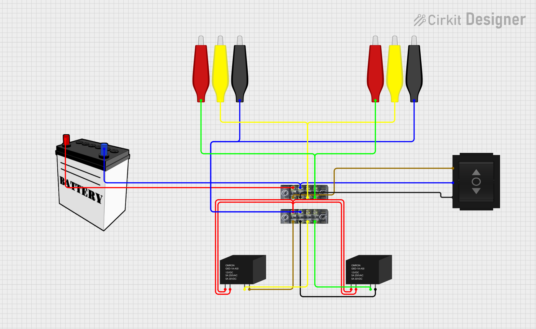
Circuit Documentation
Summary
This document provides a detailed overview of the circuit, including a list of components, wiring details, and any embedded code. The circuit consists of various components such as relays, terminal blocks, directional switches, and a 12V battery, interconnected to perform specific functions.
Component List
AdaGator Top Yellow
- Pins: wire
- Description:
- Purpose in Circuit:
AdaGator Top Red
- Pins: wire
- Description:
- Purpose in Circuit:
Terminal Block (8-pin)
- Pins: 1, 2, 3, 4, 5, 6, 7, 8
- Description:
- Purpose in Circuit:
RELAY-G5D
- Pins: COIL1, COIL2, NO, COM
- Description:
- Purpose in Circuit:
Directional Switch
- Pins: Out 2, IN, Out 1
- Description:
- Purpose in Circuit:
12V Battery
- Pins: VCC, GND
- Description:
- Purpose in Circuit:
AdaGator Top Black
- Pins: wire
- Description:
- Purpose in Circuit:
Wiring Details
AdaGator Top Yellow
- Connected Pins:
- wire connected to:
- AdaGator Top Yellow (wire)
- Terminal Block (pin 6)
- wire connected to:
AdaGator Top Red
- Connected Pins:
- wire connected to:
- AdaGator Top Red (wire)
- Terminal Block (pin 8)
- wire connected to:
Terminal Block (8-pin)
- Connected Pins:
- Pin 1 connected to:
- RELAY-G5D (COIL1, COIL2)
- 12V Battery (VCC)
- Pin 2 connected to:
- RELAY-G5D (COM)
- Directional Switch (Out 1)
- Pin 3 connected to:
- AdaGator Top Black (wire)
- Directional Switch (IN)
- Pin 4 connected to:
- RELAY-G5D (COM)
- Directional Switch (Out 2)
- Pin 6 connected to:
- RELAY-G5D (NO)
- AdaGator Top Yellow (wire)
- Pin 8 connected to:
- RELAY-G5D (NO)
- AdaGator Top Red (wire)
- Pin 1 connected to:
RELAY-G5D
- Connected Pins:
- COIL1 connected to:
- Terminal Block (pin 1)
- COIL2 connected to:
- Terminal Block (pin 1)
- COM connected to:
- Terminal Block (pin 2)
- Terminal Block (pin 4)
- NO connected to:
- Terminal Block (pin 6)
- Terminal Block (pin 8)
- COIL1 connected to:
Directional Switch
- Connected Pins:
- Out 1 connected to:
- Terminal Block (pin 2)
- IN connected to:
- Terminal Block (pin 3)
- Out 2 connected to:
- Terminal Block (pin 4)
- Out 1 connected to:
12V Battery
- Connected Pins:
- VCC connected to:
- Terminal Block (pin 1)
- GND connected to:
- Directional Switch (IN)
- Terminal Block (pin 3)
- VCC connected to:
AdaGator Top Black
- Connected Pins:
- wire connected to:
- Terminal Block (pin 3)
- wire connected to:
Embedded Code
There is no embedded code provided for this circuit.
This document provides a comprehensive overview of the circuit, detailing each component and its connections. If there are any updates or changes to the circuit, please ensure this documentation is updated accordingly.