
Arduino UNO and ESP8266 WiFi-Controlled Lighting System with Motion and Light Sensing
View and Edit Project In Cirkit Designer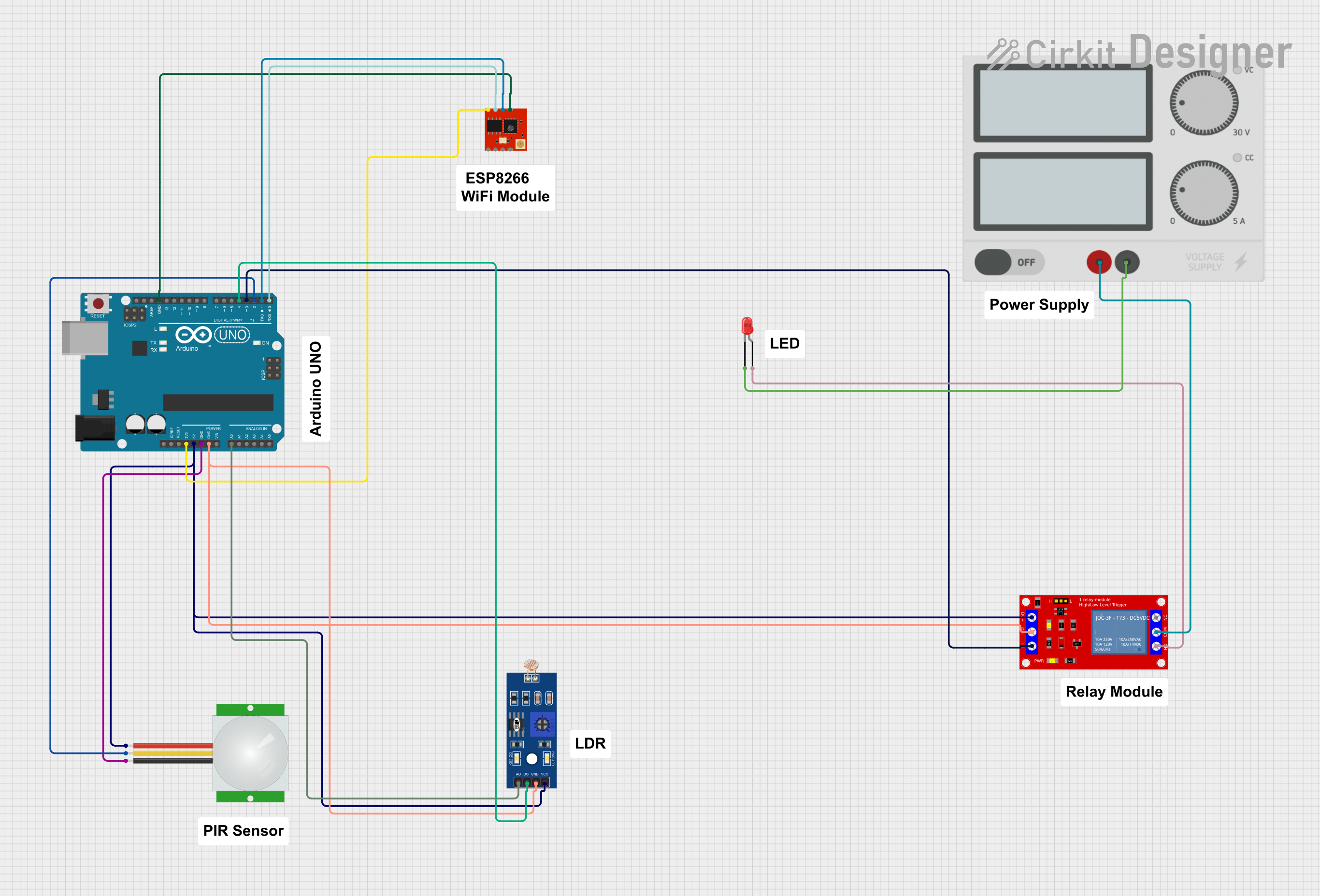
Circuit Documentation
Summary
This circuit integrates various components to form a system that likely serves as a sensor network with actuation capabilities. The Arduino UNO serves as the central microcontroller, interfacing with an ESP8266 ESP-02 WiFi module for wireless communication, a PIR sensor for motion detection, an LDR (Light Dependent Resistor) for light sensing, and a relay module for controlling an external circuit, which in this case is connected to an LED. The power supply provides the necessary voltage to the relay, which switches the LED on or off based on the control signal from the Arduino.
Component List
Arduino UNO
- Microcontroller board based on the ATmega328P
- Provides I/O pins for interfacing with various sensors and modules
1 Channel 5V Relay Module
- Electromechanical switch that allows control of a high power circuit by a low power signal
- Has Normally Open (N.O.), Common (COM), and Normally Closed (N.C.) terminals for switching
LDR (Light Dependent Resistor)
- A sensor that changes resistance based on the ambient light level
- Used to detect light intensity
PIR Sensor
- Passive Infrared Sensor used for motion detection
- Outputs a signal when motion is detected
LED: Two Pin (red)
- A simple red light-emitting diode
- Indicates the status of the relay or can be used as a general indicator
ESP8266 ESP-02 WiFi Module
- A WiFi module that enables wireless communication
- Can be used for remote monitoring and control
Power Supply
- Provides the necessary voltage and current to power the circuit components
Wiring Details
Arduino UNO
3.3Vconnected to ESP8266 ESP-02 WiFi Module VCC5Vconnected to PIR sensor VDD, LDR VCC, and Relay Module VCC+GNDconnected to PIR sensor GND, LDR GND, Relay Module VCC- (GND), and ESP8266 ESP-02 WiFi Module GNDA0connected to LDR A0D4connected to LDR D0D3connected to Relay Module IND2connected to PIR sensor SIGD1connected to ESP8266 ESP-02 WiFi Module RXDD0connected to ESP8266 ESP-02 WiFi Module TXD
1 Channel 5V Relay Module
VCC+connected to Arduino UNO 5VVCC- (GND)connected to Arduino UNO GNDINconnected to Arduino UNO D3N.O.connected to LED anodeCOMconnected to Power Supply +
LDR
A0connected to Arduino UNO A0D0connected to Arduino UNO D4GNDconnected to Arduino UNO GNDVCCconnected to Arduino UNO 5V
PIR Sensor
VDDconnected to Arduino UNO 5VSIGconnected to Arduino UNO D2GNDconnected to Arduino UNO GND
LED: Two Pin (red)
anodeconnected to Relay Module N.O.cathodeconnected to Power Supply -
ESP8266 ESP-02 WiFi Module
VCCconnected to Arduino UNO 3.3VGNDconnected to Arduino UNO GNDTXDconnected to Arduino UNO D0RXDconnected to Arduino UNO D1
Power Supply
+connected to Relay Module COM-connected to LED cathode
Documented Code
Arduino UNO Code (sketch.ino)
void setup() {
  // put your setup code here, to run once:

}

void loop() {
  // put your main code here, to run repeatedly:

}
The provided code is a template with empty setup() and loop() functions. The setup() function is intended for initialization code that runs once at startup, such as pin mode configurations. The loop() function contains the main logic of the program, which runs repeatedly after the setup() is complete. Actual implementation details need to be added to these functions based on the desired behavior of the circuit.