
Arduino UNO-Based Distance Measurement and Display with Bluetooth Connectivity
View and Edit Project In Cirkit Designer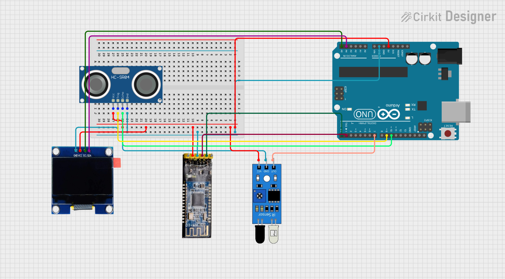
Circuit Documentation
Summary of the Circuit
This circuit integrates an Arduino UNO microcontroller with several peripherals: an infrared (IR) sensor, an HC-SR04 ultrasonic sensor, an OLED 1.3" display, and a Bluetooth module HM-10. The Arduino UNO serves as the central processing unit, interfacing with the sensors for input, the OLED display for output, and the Bluetooth module for wireless communication.
Component List
Arduino UNO
- Microcontroller board based on the ATmega328P
- It has 14 digital input/output pins, 6 analog inputs, a 16 MHz quartz crystal, a USB connection, a power jack, an ICSP header, and a reset button.
IR Sensor
- An infrared sensor capable of detecting obstacles and measuring distances.
HC-SR04 Ultrasonic Sensor
- An ultrasonic distance sensor that provides 2cm to 400cm of non-contact measurement functionality with a ranging accuracy that can reach up to 3mm.
OLED 1.3" Display
- A small display that uses organic light-emitting diodes to provide high contrast and wide viewing angles.
Bluetooth Module HM-10
- A Bluetooth 4.0 module that allows for wireless communication with other Bluetooth-enabled devices.
Wiring Details
Arduino UNO
- 5V connected to the VCC pins of the IR sensor, Bluetooth module HM-10, OLED 1.3" display, and HC-SR04 ultrasonic sensor.
- GND connected to the GND pins of the IR sensor, Bluetooth module HM-10, OLED 1.3" display, and HC-SR04 ultrasonic sensor.
- D10 connected to the ECHO pin of the HC-SR04 ultrasonic sensor.
- D9 connected to the TRIG pin of the HC-SR04 ultrasonic sensor.
- A4 (SDA) connected to the SDA pin of the OLED 1.3" display.
- A5 (SCL) connected to the SCL pin of the OLED 1.3" display.
- D7 connected to the OUT pin of the IR sensor.
- D1 (TX) connected to the RX pin of the Bluetooth module HM-10.
- D0 (RX) connected to the TX pin of the Bluetooth module HM-10.
IR Sensor
- OUT connected to the D7 pin of the Arduino UNO.
- GND connected to the GND pin of the Arduino UNO.
- VCC connected to the 5V pin of the Arduino UNO.
HC-SR04 Ultrasonic Sensor
- VCC connected to the 5V pin of the Arduino UNO.
- TRIG connected to the D9 pin of the Arduino UNO.
- ECHO connected to the D10 pin of the Arduino UNO.
- GND connected to the GND pin of the Arduino UNO.
OLED 1.3" Display
- GND connected to the GND pin of the Arduino UNO.
- VCC connected to the 5V pin of the Arduino UNO.
- SCL connected to the A5 pin of the Arduino UNO.
- SDA connected to the A4 pin of the Arduino UNO.
Bluetooth Module HM-10
- RX connected to the D0 pin of the Arduino UNO.
- TX connected to the D1 pin of the Arduino UNO.
- GND connected to the GND pin of the Arduino UNO.
- VCC connected to the 5V pin of the Arduino UNO.
Documented Code
Arduino UNO Code (sketch.ino)
void setup() {
  // put your setup code here, to run once:

}

void loop() {
  // put your main code here, to run repeatedly:

}
Note: The provided code is a template and does not include specific functionality. It should be populated with the logic required to interface with the connected components.