Cirkit Designer
Your all-in-one circuit design IDE
Home /
Project Documentation
Arduino Uno R3 LED Blinker with SIM800L GSM Module
Circuit Documentation
Summary
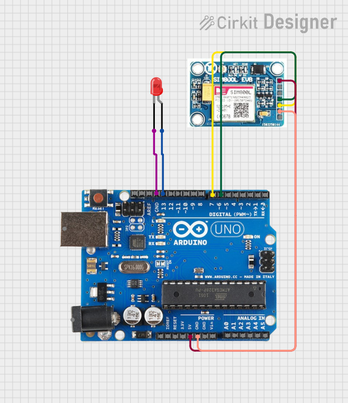
This circuit consists of an Arduino Uno R3 microcontroller, a red LED, and a SIM 800L V2.0 GSM module. The Arduino Uno R3 controls the LED, turning it on for 2 seconds and off for 3 seconds repeatedly. Additionally, the Arduino communicates with the SIM 800L module for GSM functionalities.
Component List
Arduino Uno R3
- Description: A microcontroller board based on the ATmega328P.
- Pins: D8, D9, D10, D11, D12, D13, GND, AREF, SDA, SCL, D0/RX, D1/Tx, D2, D3, D4, D5, 6, D7, A5/SCL, A4/SDA, A3, A2, A1, A0, Vin, 5V, 3.3V, RESET, IOREF, NONE, USB Jack, Power Jack
LED: Two Pin (red)
- Description: A standard red LED with two pins.
- Pins: cathode, anode
SIM 800L V2.0 GSM
- Description: A GSM module for communication over cellular networks.
- Pins: SIM_TXD, VDD, SIM.RXD, 5V/4V, GND, RST
Wiring Details
Arduino Uno R3
- D13: Connected to the anode of the LED.
- GND: Connected to the cathode of the LED.
- 6: Connected to SIM_TXD of the SIM 800L GSM module.
- D7: Connected to SIM.RXD of the SIM 800L GSM module.
- GND: Connected to GND of the SIM 800L GSM module.
- 5V: Connected to 5V/4V of the SIM 800L GSM module.
LED: Two Pin (red)
- anode: Connected to D13 of the Arduino Uno R3.
- cathode: Connected to GND of the Arduino Uno R3.
SIM 800L V2.0 GSM
- SIM_TXD: Connected to pin 6 of the Arduino Uno R3.
- SIM.RXD: Connected to pin D7 of the Arduino Uno R3.
- GND: Connected to GND of the Arduino Uno R3.
- 5V/4V: Connected to 5V of the Arduino Uno R3.
Code Documentation
Arduino Sketch
/*
 * This Arduino Sketch turns an LED on for 2 seconds and off for 3 seconds
 * repeatedly. The LED is connected to digital pin 13 on the Arduino Uno R3.
 */

void setup() {
  // Initialize digital pin 13 as an output.
  pinMode(13, OUTPUT);
}

void loop() {
  // Turn the LED on (HIGH is the voltage level)
  digitalWrite(13, HIGH);
  // Wait for 2 seconds
  delay(2000);
  // Turn the LED off by making the voltage LOW
  digitalWrite(13, LOW);
  // Wait for 3 seconds
  delay(3000);
}
- File Name: sketch.ino
- Description: This code initializes digital pin 13 as an output and toggles the LED connected to it on and off with specified delays.