
Arduino-Controlled 4-Channel RF Decoder Data Display with I2C LCD Interface
View and Edit Project In Cirkit Designer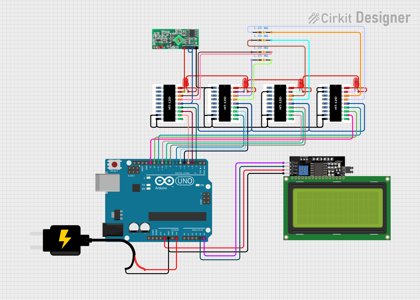
Circuit Documentation
Summary of the Circuit
This circuit comprises multiple decoders, an Arduino UNO microcontroller, a 433 MHz RF receiver module, resistors, LEDs, an LCD display, and a DC power source. The decoders are used to receive signals and convert them into a usable format. The Arduino UNO reads the output from these decoders and displays the data on a 20x4 I2C LCD. The RF receiver module is likely used to receive wireless signals that are then fed into the decoders. The resistors may be used for current limiting or pull-up/pull-down purposes. The LEDs are used as indicators, and the DC source provides a 5V supply to the circuit.
Component List
Decoders
- Component Name: Decoder, 2/12 Series, CMOS, 2.4 V to 12 V, DIP-18
- Description: A CMOS-based decoder with an 18-pin DIP package, operating between 2.4V to 12V.
Microcontroller
- Component Name: Arduino UNO
- Description: An open-source microcontroller board based on the ATmega328P, equipped with a set of digital and analog input/output pins.
RF Receiver Module
- Component Name: 433 MHz RF Receiver Module
- Description: A wireless radio frequency receiver operating at 433 MHz, commonly used for remote control applications.
Resistors
- Component Name: Resistor
- Description: A passive two-terminal electrical component that implements electrical resistance as a circuit element.
- Value: 1 MΩ (1,000,000 Ohms)
LEDs
- Component Name: LED: Two Pin (red)
- Description: A basic red light-emitting diode with two pins, an anode, and a cathode.
LCD Display
- Component Name: LCD Display 20x4 I2C
- Description: A 20x4 character LCD display with an I2C interface for displaying text and characters.
DC Source
- Component Name: DC Source 5V
- Description: A direct current power source providing a 5V output.
Wiring Details
Decoders
- Decoder Pins:
- A0-A7: Address inputs
- GND: Ground
- D0-D3: Data outputs
- DI: Data input
- OSC1, OSC2: Oscillator pins
- VT: Valid transmission indicator
- VCC: Positive supply voltage
Arduino UNO
- Arduino Pins:
- Digital I/O: D0-D13
- Analog Inputs: A0-A5
- Power: 3.3V, 5V, GND, Vin, IOREF
- Others: Reset, AREF, SCL, SDA
433 MHz RF Receiver Module
- RF Receiver Pins:
- VCC: Positive supply voltage
- DATA: Data output
- GND: Ground
Resistors
- Resistor Pins:
- pin1, pin2: Connect to other components as per circuit requirements
LEDs
- LED Pins:
- anode: Positive side
- cathode: Negative side
LCD Display 20x4 I2C
- LCD Pins:
- SCL: I2C clock
- SDA: I2C data
- VCC: Positive supply voltage
- GND: Ground
DC Source 5V
- DC Source Pins:
- VCC: Positive supply voltage
- GND: Ground
Documented Code
/*
 * This Arduino sketch receives 3-bit data from each of the four decoders
 * and displays the received data on a 20x4 I2C LCD. The data is read from
 * the digital pins connected to the decoders and displayed in binary format.
 */

#include <LiquidCrystal_I2C.h>
#include <Wire.h>

// Initialize LCD
LiquidCrystal_I2C lcd(0x27, 20, 4);

// Define input pins for each decoder
const int decoder1Pins[3] = {2, 3, 4};
const int decoder2Pins[3] = {5, 6, 7};
const int decoder3Pins[3] = {8, 9, 10};
const int decoder4Pins[3] = {11, 12, 13};

void setup() {
  // Initialize LCD
  lcd.init();
  lcd.backlight();
  lcd.clear();
  lcd.setCursor(0, 0);
  lcd.print("Decoder Data:");

  // Initialize input pins
  for (int i = 0; i < 3; i++) {
    pinMode(decoder1Pins[i], INPUT);
    pinMode(decoder2Pins[i], INPUT);
    pinMode(decoder3Pins[i], INPUT);
    pinMode(decoder4Pins[i], INPUT);
  }
}

void loop() {
  // Read data from each decoder
  int decoder1Data = readDecoderData(decoder1Pins);
  int decoder2Data = readDecoderData(decoder2Pins);
  int decoder3Data = readDecoderData(decoder3Pins);
  int decoder4Data = readDecoderData(decoder4Pins);

  // Display data on LCD
  lcd.setCursor(0, 1);
  lcd.print("D1: ");
  lcd.print(decoder1Data, BIN);
  lcd.setCursor(0, 2);
  lcd.print("D2: ");
  lcd.print(decoder2Data, BIN);
  lcd.setCursor(0, 3);
  lcd.print("D3: ");
  lcd.print(decoder3Data, BIN);
  lcd.setCursor(10, 1);
  lcd.print("D4: ");
  lcd.print(decoder4Data, BIN);

  delay(500);
}

// Function to read 3-bit data from a decoder
int readDecoderData(const int pins[3]) {
  int data = 0;
  for (int i = 0; i < 3; i++) {
    data |= (digitalRead(pins[i]) << i);
  }
  return data;
}
This code is designed to work with the Arduino UNO microcontroller. It initializes the LCD display and sets up the input pins connected to the decoders. In the main loop, it reads the 3-bit data from each decoder and displays it on the LCD in binary format. The readDecoderData function is a utility to read the data from the decoder pins.