
Arduino Nano and ESP32-CAM Controlled LED Array with Servo Motor Interaction
View and Edit Project In Cirkit Designer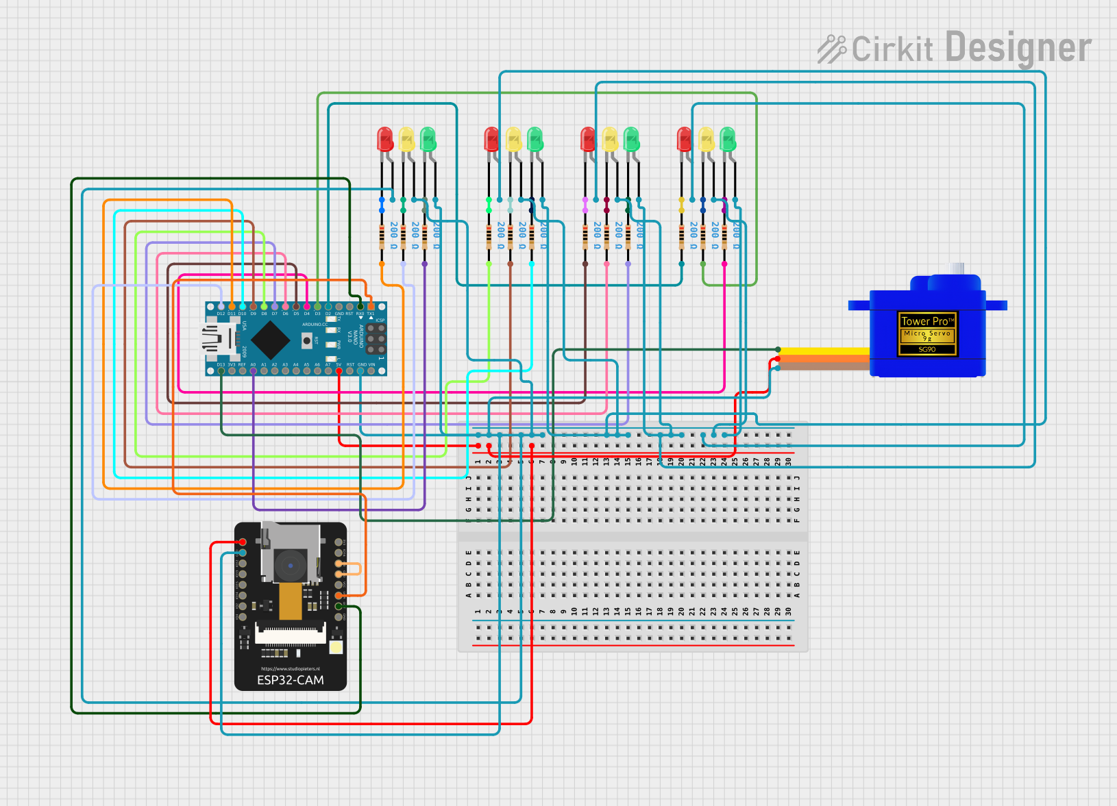
Circuit Documentation
Summary
This circuit integrates an ESP32-CAM module, an Arduino Nano, a Servomotor SG90, and multiple LEDs with corresponding resistors. The ESP32-CAM is connected to the Arduino Nano for serial communication and shares a common power supply. The servomotor is controlled by the Arduino Nano and is also powered by the same 5V supply. The LEDs are connected to various digital pins on the Arduino Nano through 200 Ohm resistors, and they share a common ground with the rest of the circuit.
Component List
Microcontrollers
- ESP32-CAM: A small-sized ESP32-based module with Wi-Fi and camera capabilities.
- Arduino Nano: A compact board based on the ATmega328P microcontroller, with digital and analog I/O pins.
Actuators
- Servomotor SG90: A small and lightweight servo motor suitable for various control applications.
Indicators
- LED: Two Pin (red): A basic red LED for indication purposes.
- LED: Two Pin (green): A basic green LED for indication purposes.
- LED: Two Pin (yellow): A basic yellow LED for indication purposes.
Passive Components
- Resistor: A 200 Ohm resistor used to limit current through the LEDs.
Wiring Details
ESP32-CAM
- 5V connected to the 5V output from the Arduino Nano.
- GND connected to the common ground.
- VOR connected to the TX pin of the Arduino Nano.
- VOT connected to the RX pin of the Arduino Nano.
- IO0 connected to GND (for programming mode, if necessary).
Arduino Nano
- 5V output provides power to the ESP32-CAM and Servomotor SG90.
- GND is the common ground for the entire circuit.
- Digital Pins (D2-D13) connected to the anodes of LEDs through 200 Ohm resistors.
- D1/TX connected to VOR of the ESP32-CAM.
- D0/RX connected to VOT of the ESP32-CAM.
- D13/SCK connected to the signal pin of the Servomotor SG90.
Servomotor SG90
- SIG connected to D13/SCK on the Arduino Nano.
- VCC connected to the 5V output from the Arduino Nano.
- GND connected to the common ground.
LEDs
- Anode of each LED connected to various digital pins on the Arduino Nano through 200 Ohm resistors.
- Cathode of each LED connected to the common ground.
Resistors
- Each 200 Ohm resistor is connected in series with an LED between the anode and a digital pin on the Arduino Nano.
Documented Code
Arduino Nano Code (sketch.ino)
void setup() {
  // put your setup code here, to run once:

}

void loop() {
  // put your main code here, to run repeatedly:

}
Additional Notes (documentation.txt)
No additional code documentation provided.