
Arduino UNO Based Temperature Monitoring System with OLED Display
View and Edit Project In Cirkit Designer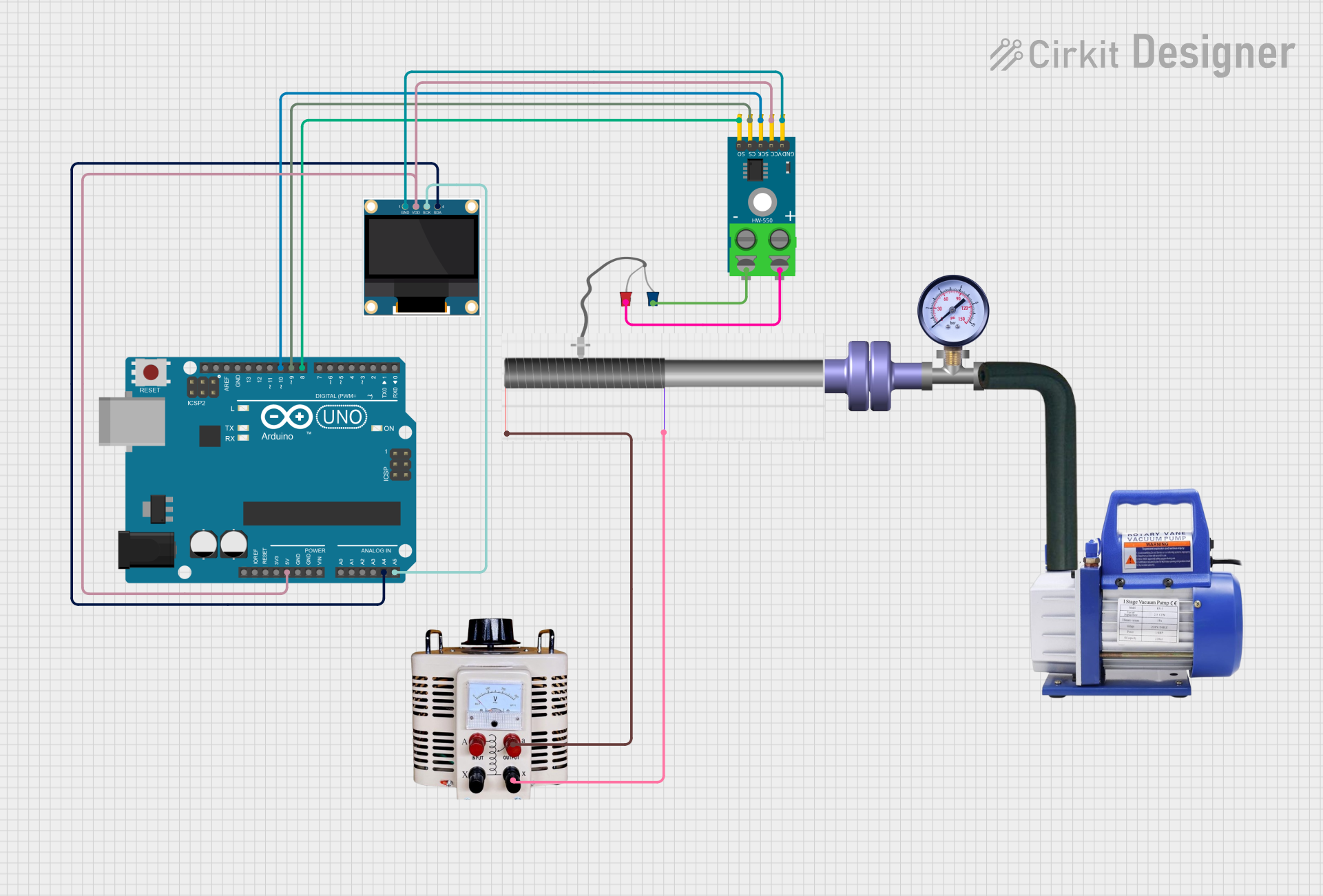
Circuit Documentation
Summary of the Circuit
The circuit described in the provided inputs consists of an Arduino UNO microcontroller interfaced with a MAX6675 thermocouple-to-digital converter module, a 0.96" OLED display, a quartz crystal, a variable transformer, a K-type thermocouple, and additional components such as a flange, rotary pump, pressure gauge, and hose which do not have direct electrical connections in the net list provided.
The Arduino UNO is programmed to interact with the MAX6675 module to read temperature data from the K-type thermocouple and display the readings on the OLED screen. The quartz crystal and variable transformer are connected, suggesting a timing or frequency control application, although specific details are not provided.
Component List
Arduino UNO
- Microcontroller board based on the ATmega328P
- Provides digital and analog I/O pins
- Used for controlling the circuit logic and interfacing with other modules
MAX6675 Module
- Thermocouple-to-digital converter
- Interfaces with a K-type thermocouple to measure temperature
- Communicates with the Arduino UNO via SPI
0.96" OLED
- Small organic light-emitting diode display
- Used for displaying information such as temperature readings
- Communicates with the Arduino UNO via I2C
Quartz
- Piezoelectric crystal used for timing and frequency control
Variable Transformer
- An adjustable transformer used to vary voltage output
- Connected to the quartz, suggesting a role in frequency or voltage control
K-type Thermocouple
- A sensor used to measure high temperatures
- Connected to the MAX6675 module for temperature readings
Flange, Rotary Pump, Pressure Gauge, Hose
- These components are listed but do not have electrical connections in the provided net list
- Likely part of a larger system that includes fluid or gas handling
Wiring Details
Arduino UNO
5Vconnected toVCCof MAX6675 Module andVDDof 0.96" OLEDA4(SDA) connected toSDAof 0.96" OLEDA5(SCL) connected toSCKof 0.96" OLEDD10connected toSCKof MAX6675 ModuleD9connected toCSof MAX6675 ModuleD8connected toSOof MAX6675 Module
MAX6675 Module
GNDconnected toGNDof 0.96" OLEDVCCconnected to5Vof Arduino UNOSCKconnected toD10of Arduino UNOCSconnected toD9of Arduino UNOSOconnected toD8of Arduino UNO-connected to1of K-type Thermocouple+connected to2of K-type Thermocouple
0.96" OLED
GNDconnected toGNDof MAX6675 ModuleVDDconnected to5Vof Arduino UNOSDAconnected toA4of Arduino UNOSCKconnected toA5of Arduino UNO
Quartz
1connected to2of Variable Transformer2connected to2of Variable Transformer
K-type Thermocouple
1connected to-of MAX6675 Module2connected to+of MAX6675 Module
Documented Code
/*
 * This Arduino sketch controls a traffic light system using a joystick module.
 * When the joystick is moved up, the red LED turns on.
 * When the joystick is moved left, the yellow LED turns on.
 * When the joystick is moved right, the green LED turns on.
 * When the joystick is moved down, all LEDs turn on.
 */

// Pin definitions
const int VRX_PIN = A0; // Joystick X-axis
const int VRY_PIN = A1; // Joystick Y-axis
const int SW_PIN = 7;   // Joystick button (not used)
const int RED_LED_PIN = 2;   // Red LED
const int YELLOW_LED_PIN = 3; // Yellow LED
const int GREEN_LED_PIN = 4;  // Green LED

void setup() {
  // Initialize serial communication
  Serial.begin(9600);

  // Set LED pins as outputs
  pinMode(RED_LED_PIN, OUTPUT);
  pinMode(YELLOW_LED_PIN, OUTPUT);
  pinMode(GREEN_LED_PIN, OUTPUT);

  // Set joystick button pin as input
  pinMode(SW_PIN, INPUT);
}

void loop() {
  // Read joystick values
  int xValue = analogRead(VRX_PIN);
  int yValue = analogRead(VRY_PIN);

  // Determine joystick direction
  if (yValue < 300) { // Joystick moved up
    digitalWrite(RED_LED_PIN, HIGH);
    digitalWrite(YELLOW_LED_PIN, LOW);
    digitalWrite(GREEN_LED_PIN, LOW);
  } else if (xValue < 300) { // Joystick moved left
    digitalWrite(RED_LED_PIN, LOW);
    digitalWrite(YELLOW_LED_PIN, HIGH);
    digitalWrite(GREEN_LED_PIN, LOW);
  } else if (xValue > 700) { // Joystick moved right
    digitalWrite(RED_LED_PIN, LOW);
    digitalWrite(YELLOW_LED_PIN, LOW);
    digitalWrite(GREEN_LED_PIN, HIGH);
  } else if (yValue > 700) { // Joystick moved down
    digitalWrite(RED_LED_PIN, HIGH);
    digitalWrite(YELLOW_LED_PIN, HIGH);
    digitalWrite(GREEN_LED_PIN, HIGH);
  } else { // Joystick in neutral position
    digitalWrite(RED_LED_PIN, LOW);
    digitalWrite(YELLOW_LED_PIN, LOW);
    digitalWrite(GREEN_LED_PIN, LOW);
  }

  // Small delay to stabilize readings
  delay(100);
}
Note: The provided code does not match the described functionality of the circuit. The code appears to control a traffic light system using a joystick, which is not part of the circuit described in the inputs. This discrepancy should be addressed for accurate documentation.