Raspberry Pi 4B Servomotor Control System with Rotary Encoder Input
Circuit Documentation
Summary
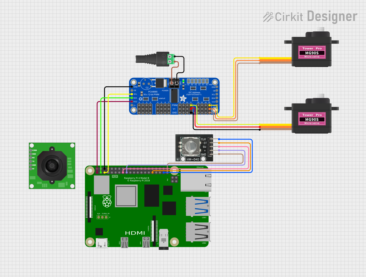
The circuit in question is designed to interface a Raspberry Pi 4B with various peripherals including servomotors, a PWM servo breakout board, a rotary encoder, and a power supply module. The Raspberry Pi 4B serves as the central processing unit, controlling the servomotors via the Adafruit PCA9685 PWM Servo Breakout board. The rotary encoder is directly connected to the Raspberry Pi for user input. Power is supplied to the circuit through a 2.1mm Barrel Jack with Terminal Block, which provides power to the PWM breakout board and subsequently to the servomotors.
Component List
Raspberry Pi 4B
- A single-board computer with multiple GPIO pins for interfacing with various components.
Servomotor MG90S (2 units)
- A small and lightweight servomotor suitable for applications that require precise control.
Adafruit PCA9685 PWM Servo Breakout
- A 16-channel, 12-bit PWM breakout board used for controlling multiple servomotors.
TTL Serial JPEG Camera
- A camera module capable of capturing JPEG images, interfacing via serial communication.
HW-040 Rotary Encoder
- An input device that provides rotational feedback and can be used for navigation through menus or adjusting settings.
2.1mm Barrel Jack with Terminal Block
- A power connector that allows for easy connection to an external power supply.
Wiring Details
Raspberry Pi 4B
3V3- Powers the HW-040 Rotary Encoder.5V- Not connected.GPIO2- Connected toSDAon Adafruit PCA9685 PWM Servo Breakout for I2C communication.GPIO3- Connected toSCLon Adafruit PCA9685 PWM Servo Breakout for I2C communication.GND- Common ground for the circuit.- Other GPIOs - Not connected or used for other purposes not specified in the net list.
Servomotor MG90S
SIG- Signal input fromPWM15orPWM11on Adafruit PCA9685 PWM Servo Breakout.VCC- Power input from5.0Von Adafruit PCA9685 PWM Servo Breakout.GND- Ground connection toGNDon Adafruit PCA9685 PWM Servo Breakout.
Adafruit PCA9685 PWM Servo Breakout
PWRIN- Power input fromPOSon 2.1mm Barrel Jack with Terminal Block.GND- Ground connection toNEGon 2.1mm Barrel Jack with Terminal Block and common ground with Raspberry Pi 4B.VCC- Connected to3V3on Raspberry Pi 4B.SDAandSCL- I2C communication with Raspberry Pi 4B.PWM7toPWM0,PWM15toPWM8- PWM outputs to servomotors or not connected.5.0V- Power output to servomotors.
HW-040 Rotary Encoder
SW- Switch pin connected toGPIO22on Raspberry Pi 4B.+- Power input from3V3on Raspberry Pi 4B.DT- Data pin connected toGPIO6on Raspberry Pi 4B.CLK- Clock pin connected toGPIO26on Raspberry Pi 4B.GND- Ground connection toGNDon Raspberry Pi 4B.
2.1mm Barrel Jack with Terminal Block
POS- Positive power input toPWRINon Adafruit PCA9685 PWM Servo Breakout.NEG- Ground connection toGNDon Adafruit PCA9685 PWM Servo Breakout.
Documented Code
No code has been provided for the microcontrollers or other programmable components in the circuit. Therefore, this section is not applicable for the current documentation. If code becomes available, it should be documented here with appropriate descriptions of its functionality and usage.