
Circuit Documentation
Summary of the Circuit
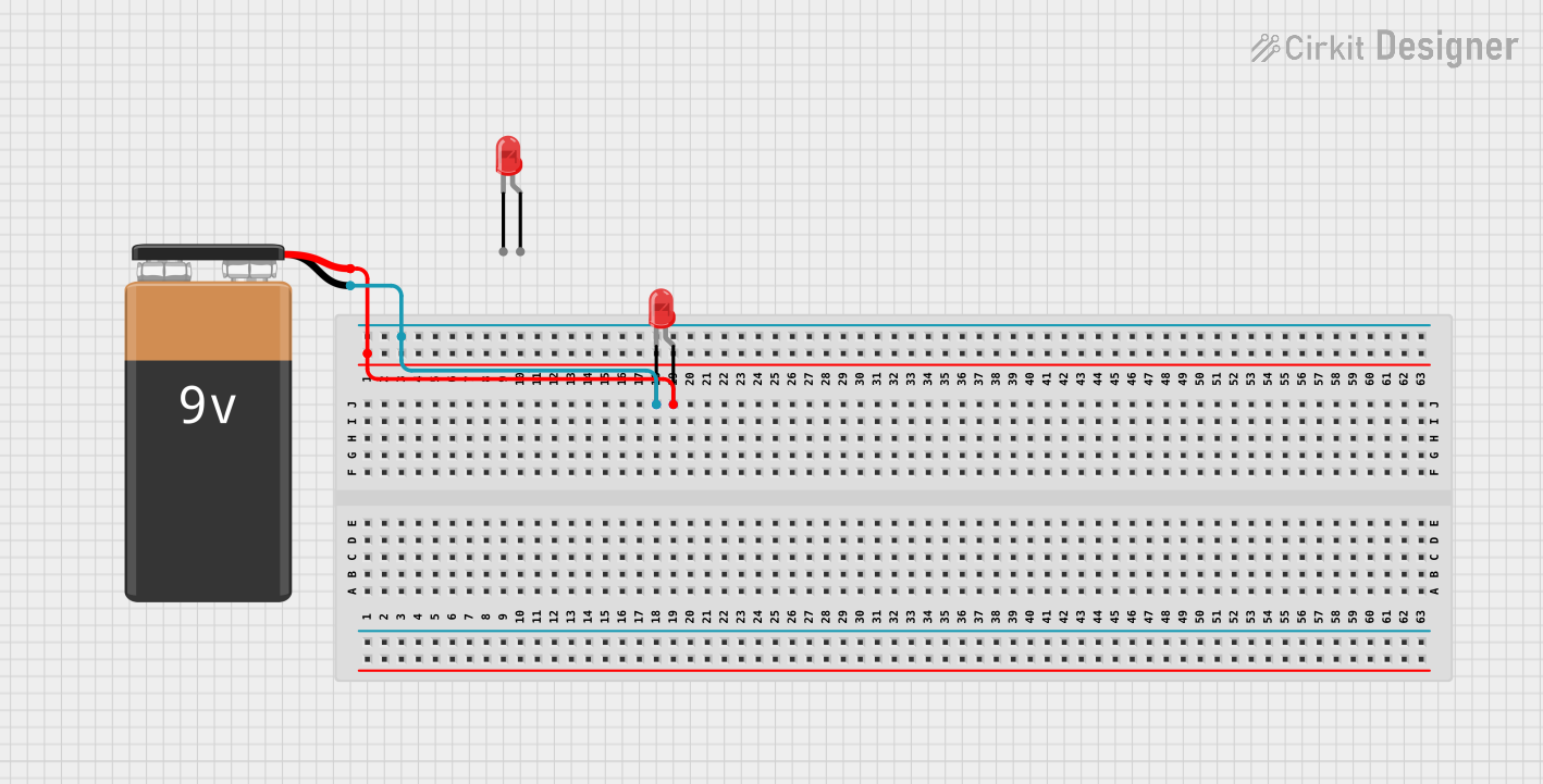
The circuit described by the provided inputs is a simple LED circuit powered by a 9V battery. The circuit consists of a single LED that is connected directly to the battery. There are no current-limiting resistors or additional control electronics involved, which is atypical for an LED circuit as it may lead to the LED being overdriven and potentially damaged. The absence of microcontroller code indicates that the LED is intended to be either always on when the battery is connected or manually switched by an unmentioned external mechanism.
Component List
9V Battery
- Description: A standard 9V battery used as the power source for the circuit.
- Pins:
- Negative (-)
- Positive (+)
LED: Two Pin (red)
- Description: A red two-pin Light Emitting Diode (LED) that emits light when powered.
- Pins:
- Cathode (negative side)
- Anode (positive side)
Wiring Details
9V Battery
- Positive (+) pin is connected to the anode of the LED.
- Negative (-) pin is connected to the cathode of the LED.
LED: Two Pin (red)
- Anode is connected to the positive (+) pin of the 9V Battery.
- Cathode is connected to the negative (-) pin of the 9V Battery.
Documented Code
There is no code provided for this circuit as there are no microcontroller components involved. The operation of the LED is purely electrical and does not involve any programmable control.
Note: The documentation does not include instance IDs as per the request. Additionally, it is important to mention that the circuit as described may not be safe for the LED without a current-limiting resistor. It is recommended to include a resistor in series with the LED to prevent it from burning out.