
Battery-Powered LED and Buzzer Control Circuit Using BC547 Transistors
View and Edit Project In Cirkit Designer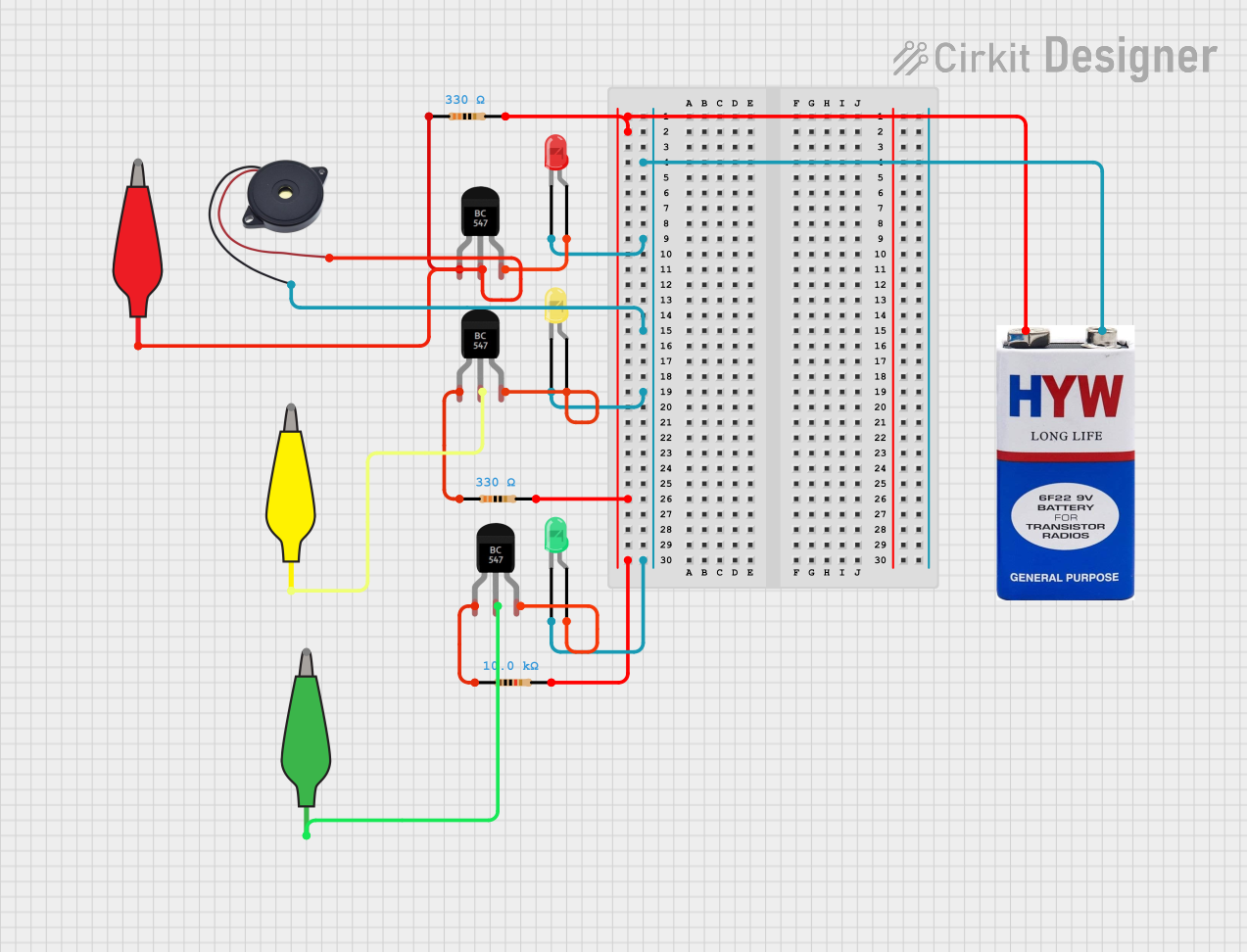
Circuit Documentation
Summary
This circuit consists of multiple BC547 transistors, resistors, LEDs, a buzzer, and a 9V battery. The circuit is designed to control the LEDs and buzzer using the transistors and resistors. The alligator clip cables are used to make connections between various components.
Component List
BC547 Transistor
- Pins: Collector, Base, Emitter
- Description: NPN Bipolar Junction Transistor
Resistor
- Pins: pin1, pin2
- Description: Fixed Resistor
- Properties:
- Resistance: 330 Ohms
Resistor
- Pins: pin1, pin2
- Description: Fixed Resistor
- Properties:
- Resistance: 10,000 Ohms
LED: Two Pin (red)
- Pins: cathode, anode
- Description: Red Light Emitting Diode
LED: Two Pin (green)
- Pins: cathode, anode
- Description: Green Light Emitting Diode
LED: Two Pin (yellow)
- Pins: cathode, anode
- Description: Yellow Light Emitting Diode
Buzzer
- Pins: GND, IN
- Description: Piezoelectric Buzzer
9V battery
- Pins: +, -
- Description: 9V Power Supply
12978-alligator_clip_cable_half-red
- Pins: Pin, Alligator
- Description: Red Alligator Clip Cable
12978-alligator_clip_cable_half-yellow
- Pins: Pin, Alligator
- Description: Yellow Alligator Clip Cable
12978-alligator_clip_cable_half-green
- Pins: Pin, Alligator
- Description: Green Alligator Clip Cable
Wiring Details
9V Battery
+ is connected to:
- Resistor (pin2) with 330 Ohms
- Resistor (pin2) with 330 Ohms
- Resistor (pin2) with 10,000 Ohms
- is connected to:
- Red LED (cathode)
- Buzzer (GND)
- Yellow LED (cathode)
- Green LED (cathode)
BC547 Transistor
Collector of the first transistor is connected to:
- Resistor (pin1) with 330 Ohms
Base of the first transistor is connected to:
- Red Alligator Clip Cable (Pin)
- Buzzer (IN)
Emitter of the first transistor is connected to:
- Red LED (anode)
Collector of the second transistor is connected to:
- Resistor (pin1) with 10,000 Ohms
Base of the second transistor is connected to:
- Green Alligator Clip Cable (Pin)
Emitter of the second transistor is connected to:
- Green LED (anode)
Collector of the third transistor is connected to:
- Resistor (pin1) with 330 Ohms
Base of the third transistor is connected to:
- Yellow Alligator Clip Cable (Pin)
Emitter of the third transistor is connected to:
- Yellow LED (anode)
Resistors
Resistor with 330 Ohms (first instance)
- pin1 is connected to: BC547 Transistor (Collector)
- pin2 is connected to: 9V Battery (+)
Resistor with 10,000 Ohms
- pin1 is connected to: BC547 Transistor (Collector)
- pin2 is connected to: 9V Battery (+)
Resistor with 330 Ohms (second instance)
- pin1 is connected to: BC547 Transistor (Collector)
- pin2 is connected to: 9V Battery (+)
LEDs
Red LED
- cathode is connected to: 9V Battery (-)
- anode is connected to: BC547 Transistor (Emitter)
Green LED
- cathode is connected to: 9V Battery (-)
- anode is connected to: BC547 Transistor (Emitter)
Yellow LED
- cathode is connected to: 9V Battery (-)
- anode is connected to: BC547 Transistor (Emitter)
Buzzer
- GND is connected to: 9V Battery (-)
- IN is connected to: Red Alligator Clip Cable (Pin)
Alligator Clip Cables
Red Alligator Clip Cable
- Pin is connected to: Buzzer (IN)
- Alligator is connected to: BC547 Transistor (Base)
Yellow Alligator Clip Cable
- Pin is connected to: BC547 Transistor (Base)
- Alligator is connected to: BC547 Transistor (Base)
Green Alligator Clip Cable
- Pin is connected to: BC547 Transistor (Base)
- Alligator is connected to: BC547 Transistor (Base)
Code
There is no code provided for this circuit.