
Arduino Uno R3 Controlled Servos with NRF24L01 Wireless Communication
View and Edit Project In Cirkit Designer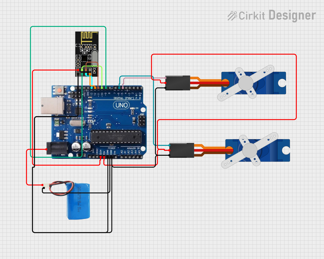
Circuit Documentation
Summary of the Circuit
This circuit is designed to interface an Arduino Uno R3 with an NRF24L01 wireless transceiver module and two Tower Pro SG90 servos. The Arduino Uno R3 serves as the central processing unit, controlling the servos and communicating wirelessly through the NRF24L01 module. The servos are powered by the Arduino's 5V output, and the NRF24L01 is powered by the Arduino's 3.3V output. The 5V battery is connected to the Arduino's power jack to supply power to the circuit.
Component List
Arduino Uno R3
- Microcontroller board based on the ATmega328P
- It has 14 digital input/output pins, 6 analog inputs, a USB connection, a power jack, an ICSP header, and a reset button.
NRF24L01
- A 2.4GHz wireless transceiver module
- It has pins for SPI communication and can be powered by a 3.3V supply.
Tower Pro SG90 Servo (x2)
- A small and lightweight servo motor suitable for RC vehicles and other low-load applications.
- It operates at +5V and has a signal pin to receive PWM control signals.
5V Battery
- A power source used to supply the Arduino Uno R3 with 5V through its power jack.
Wiring Details
Arduino Uno R3
- Power Jack connected to the positive terminal of the 5V battery.
- 3.3V pin connected to the VCC (3V) of the NRF24L01.
- 5V pin connected to the +5V pins of both Tower Pro SG90 servos.
- GND pins connected to the negative terminal of the 5V battery, GND of the NRF24L01, and GND pins of both Tower Pro SG90 servos.
- Digital Pin 13 (SCK) connected to the SCK of the NRF24L01.
- Digital Pin 12 (MISO) connected to the MISO of the NRF24L01.
- Digital Pin 11 (MOSI) connected to the MOSI of the NRF24L01.
- Digital Pin 10 (CSN) connected to the CSN of the NRF24L01.
- Digital Pin 9 (CE) connected to the CE of the NRF24L01.
- Digital Pin 6 connected to the Signal pin of one Tower Pro SG90 servo.
- Digital Pin 5 connected to the Signal pin of the other Tower Pro SG90 servo.
NRF24L01
- VCC (3V) connected to the 3.3V pin of the Arduino Uno R3.
- GND connected to the GND pin of the Arduino Uno R3.
- CE connected to Digital Pin 9 of the Arduino Uno R3.
- CSN connected to Digital Pin 10 of the Arduino Uno R3.
- SCK connected to Digital Pin 13 of the Arduino Uno R3.
- MOSI connected to Digital Pin 11 of the Arduino Uno R3.
- MISO connected to Digital Pin 12 of the Arduino Uno R3.
Tower Pro SG90 Servo
- Signal pin of one servo connected to Digital Pin 6 of the Arduino Uno R3.
- Signal pin of the other servo connected to Digital Pin 5 of the Arduino Uno R3.
- +5V pins of both servos connected to the 5V pin of the Arduino Uno R3.
- GND pins of both servos connected to the GND pin of the Arduino Uno R3.
5V Battery
- Positive terminal connected to the Power Jack of the Arduino Uno R3.
- Negative terminal connected to the GND pin of the Arduino Uno R3.
Documented Code
Since no code was provided in the input, this section is left blank. Normally, this section would include the embedded code for the microcontroller, along with comments explaining the functionality of the code and how it interacts with the connected components.