Cirkit Designer
Your all-in-one circuit design IDE
Home /
Project Documentation
AC to DC Power Supply with Voltage Regulation and Multimeter Monitoring

Circuit Documentation
Summary of the Circuit
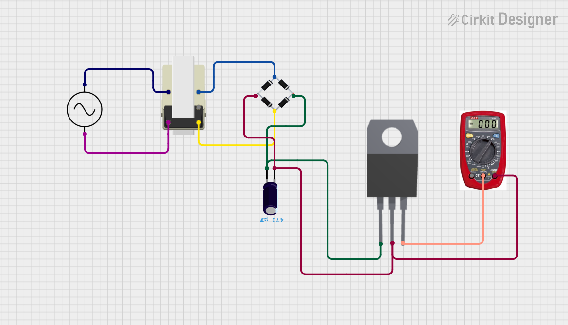
This circuit appears to be a power supply unit that takes an AC input and converts it to a regulated DC output. The AC supply is first transformed to a lower voltage level, then rectified by a bridge rectifier. The resulting pulsating DC is smoothed by an electrolytic capacitor. Finally, a 7808 voltage regulator is used to provide a stable 8V DC output. A multimeter is included in the design for measurement purposes.
Component List
Bridge Rectifier
- Description: A bridge rectifier is a device that converts an AC input into a DC output.
- Pins: Source_in-, source_out-, source_out+, source_in+
AC Supply
- Description: An AC supply provides an alternating current source.
- Pins: +ve, -ve
Transformer
- Description: A transformer is used to step down or step up the voltage level.
- Pins: 5, 1, 2, 3, 4
Electrolytic Capacitor
- Description: An electrolytic capacitor is used for filtering and smoothing the rectified DC voltage.
- Pins: -, +
- Properties: Capacitance: 0.00047 Farads
7808 Voltage Regulator
- Description: A 7808 is a voltage regulator that outputs a constant 8V DC.
- Pins: INPUT, GND, OUTPUT
Multimeter
- Description: A multimeter is used to measure electrical properties such as voltage and current.
- Pins: COM, V, A
Wiring Details
Bridge Rectifier
- Source_in-: Connected to pin 5 of the Transformer.
- source_out-: Connected to GND of 7808, COM of Multimeter, and - of Electrolytic Capacitor.
- source_out+: Connected to INPUT of 7808 and + of Electrolytic Capacitor.
- source_in+: Connected to pin 3 of the Transformer.
AC Supply
- +ve: Connected to pin 1 of the Transformer.
- -ve: Connected to pin 2 of the Transformer.
Transformer
- Pin 5: Connected to Source_in- of Bridge Rectifier.
- Pin 1: Connected to +ve of AC Supply.
- Pin 2: Connected to -ve of AC Supply.
- Pin 3: Connected to source_in+ of Bridge Rectifier.
Electrolytic Capacitor
- -: Connected to source_out- of Bridge Rectifier, GND of 7808, and COM of Multimeter.
- +: Connected to source_out+ of Bridge Rectifier and INPUT of 7808.
7808 Voltage Regulator
- INPUT: Connected to source_out+ of Bridge Rectifier and + of Electrolytic Capacitor.
- GND: Connected to source_out- of Bridge Rectifier, - of Electrolytic Capacitor, and COM of Multimeter.
- OUTPUT: Connected to V of Multimeter.
Multimeter
- COM: Connected to source_out- of Bridge Rectifier, GND of 7808, and - of Electrolytic Capacitor.
- V: Connected to OUTPUT of 7808.
- A: Not connected in the current configuration.
Documented Code
There is no embedded code provided for any microcontrollers in this circuit. Therefore, this section is not applicable to the current documentation.