
Wi-Fi Controlled Smart Lighting System with NodeMCU and Relay Module
View and Edit Project In Cirkit Designer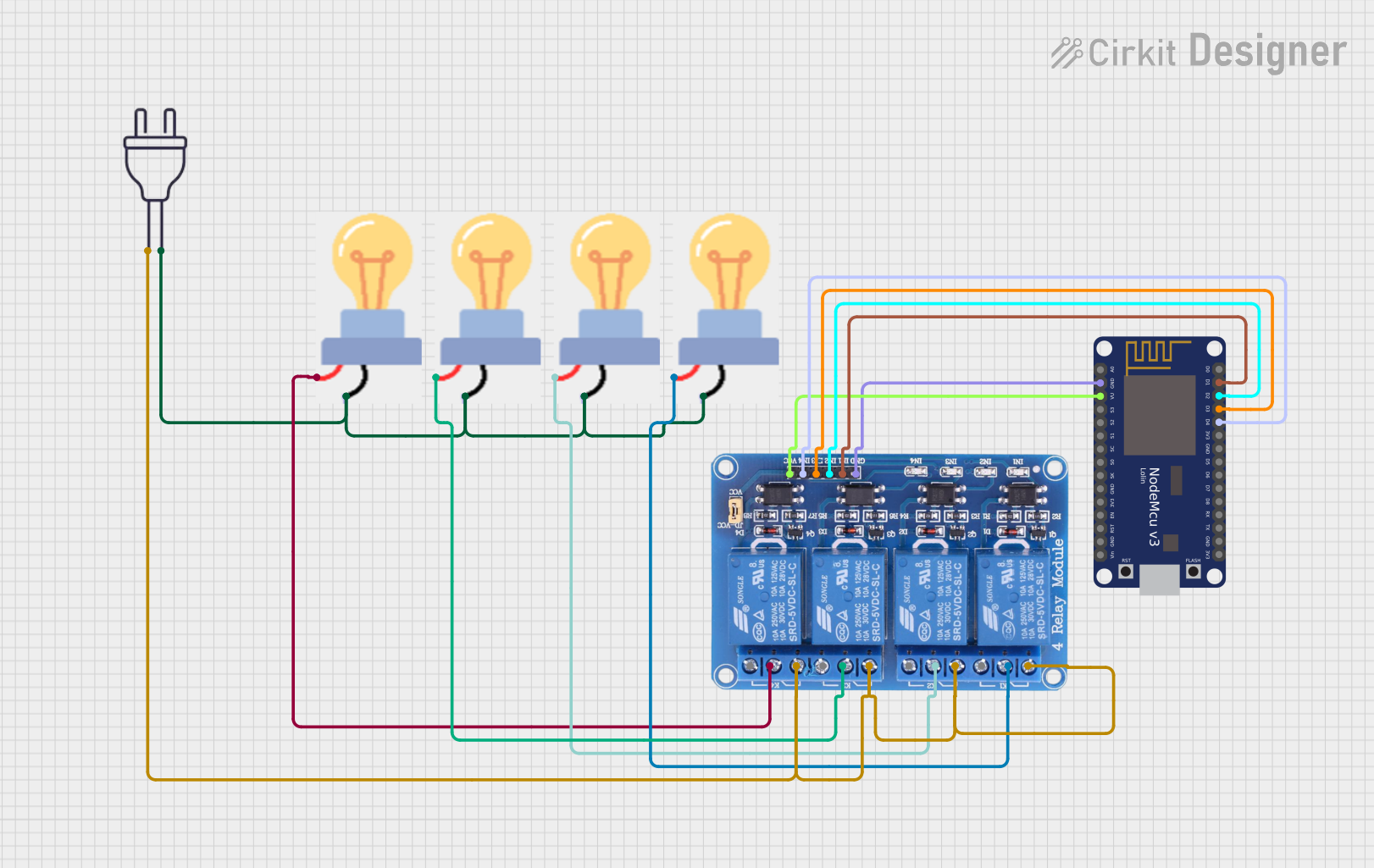
Circuit Documentation
Summary
This circuit consists of a NodeMCU V3 ESP8266 microcontroller, a 4-channel relay module, four bulbs, and a 220V power source. The NodeMCU controls the relay module, which in turn controls the power to the bulbs. The bulbs are connected to the relay module, which switches them on or off based on the signals received from the NodeMCU. The 220V power source provides the necessary power for the bulbs.
Component List
NodeMCU V3 ESP8266
- Pins: A0, GND, VU, S3, S2, S1, SC, S0, SK, 3V3, EN, RST, Vin, D0, D1, D2, D3, D4, D5, D6, D7, D8, RX, TX
- Description: A low-cost Wi-Fi microcontroller with GPIO, PWM, ADC, I2C, and 1-Wire capabilities.
- Purpose: To control the relay module based on programmed logic.
Relay 4 Channel 5V
- Pins: GND, IN1, IN2, IN3, IN4, VCC, COM1, COM2, COM3, COM4, NO1, NO2, NO3, NO4, NC1, NC2, NC3, NC4
- Description: A relay module that allows control of high voltage devices with low voltage signals.
- Purpose: To switch the bulbs on and off based on signals from the NodeMCU.
Bulb
- Pins: GND, power
- Description: Standard electrical bulbs.
- Purpose: To provide illumination when powered.
Power 220V
- Pins: hot wire, neutral wire
- Description: Standard 220V AC power source.
- Purpose: To provide the necessary power for the bulbs.
Wiring Details
NodeMCU V3 ESP8266
- GND is connected to GND of the Relay 4 Channel 5V.
- D1 is connected to IN1 of the Relay 4 Channel 5V.
- D2 is connected to IN2 of the Relay 4 Channel 5V.
- D3 is connected to IN3 of the Relay 4 Channel 5V.
- D4 is connected to IN4 of the Relay 4 Channel 5V.
- VU is connected to VCC of the Relay 4 Channel 5V.
Relay 4 Channel 5V
- GND is connected to GND of the NodeMCU V3 ESP8266.
- IN1 is connected to D1 of the NodeMCU V3 ESP8266.
- IN2 is connected to D2 of the NodeMCU V3 ESP8266.
- IN3 is connected to D3 of the NodeMCU V3 ESP8266.
- IN4 is connected to D4 of the NodeMCU V3 ESP8266.
- VCC is connected to VU of the NodeMCU V3 ESP8266.
- COM1 is connected to power of the first bulb.
- COM2 is connected to power of the second bulb.
- COM3 is connected to power of the third bulb.
- COM4 is connected to power of the fourth bulb.
- NC1, NC2, NC3, and NC4 are connected to hot wire of the Power 220V.
Bulbs
- GND of all bulbs are connected together and to the neutral wire of the Power 220V.
- Power of the first bulb is connected to COM1 of the Relay 4 Channel 5V.
- Power of the second bulb is connected to COM2 of the Relay 4 Channel 5V.
- Power of the third bulb is connected to COM3 of the Relay 4 Channel 5V.
- Power of the fourth bulb is connected to COM4 of the Relay 4 Channel 5V.
Power 220V
- Hot wire is connected to NC1, NC2, NC3, and NC4 of the Relay 4 Channel 5V.
- Neutral wire is connected to GND of all bulbs.
Code
No code is provided for this circuit.