Cirkit Designer
Your all-in-one circuit design IDE
Home /
Project Documentation
ESP32-Powered Battery-Operated Real-Time Clock and TFT Display Module
Circuit Documentation
Summary
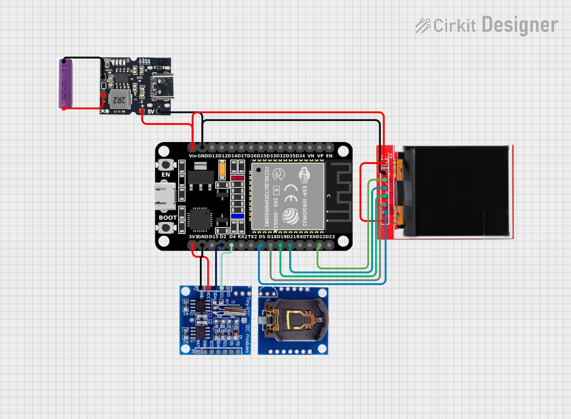
This document provides a detailed overview of a circuit that includes a TFT LCD Display, an RTC module, an ESP32 microcontroller, a Type-C Power Bank Module, and a 3.7V battery. The circuit is designed to power the components and facilitate communication between the ESP32 microcontroller, the TFT LCD Display, and the RTC module.
Component List
TFT LCD Display ST7735S
- Description: A color TFT LCD display module with an ST7735S driver.
- Pins: Vcc, GND, CS, RESET, A0, SDA, SCK, LED
RTC DS13072
- Description: A Real-Time Clock (RTC) module for keeping track of time.
- Pins: DS, SCL, SDA, VCC, GND, SQ, BAT
ESP32 (30 pin)
- Description: A powerful microcontroller with built-in Wi-Fi and Bluetooth capabilities.
- Pins: EN, VP, VN, D34, D35, D32, D33, D25, D26, D27, D14, D12, D13, GND, Vin, D23, D22, TX0, RX0, D21, D19, D18, D5, TX2, RX2, D4, D2, D15, 3V3
Type-C Power Bank Module
- Description: A module to provide power from a Type-C power bank.
- Pins: Gnd, +Ve (Bat), +5v
3.7V Battery
- Description: A rechargeable 3.7V lithium battery.
- Pins: +, -
Wiring Details
TFT LCD Display ST7735S
- Vcc connected to +5v of the Type-C Power Bank Module
- GND connected to Gnd of the Type-C Power Bank Module and GND of the ESP32
- CS connected to D22 of the ESP32
- RESET connected to D21 of the ESP32
- A0 connected to D19 of the ESP32
- SDA connected to D18 of the ESP32
- SCK connected to D5 of the ESP32
- LED connected to +5v of the Type-C Power Bank Module
RTC DS13072
- SCL connected to D4 of the ESP32
- SDA connected to D2 of the ESP32
- GND connected to GND of the ESP32
- VCC connected to 3V3 of the ESP32
ESP32 (30 pin)
- GND connected to Gnd of the Type-C Power Bank Module and GND of the TFT LCD Display and RTC DS13072
- Vin connected to +5v of the Type-C Power Bank Module
- D22 connected to CS of the TFT LCD Display
- D21 connected to RESET of the TFT LCD Display
- D19 connected to A0 of the TFT LCD Display
- D18 connected to SDA of the TFT LCD Display
- D5 connected to SCK of the TFT LCD Display
- D4 connected to SCL of the RTC DS13072
- D2 connected to SDA of the RTC DS13072
- 3V3 connected to VCC of the RTC DS13072
Type-C Power Bank Module
- Gnd connected to GND of the TFT LCD Display, GND of the ESP32, and - of the 3.7V Battery
- +5v connected to Vcc and LED of the TFT LCD Display and Vin of the ESP32
- +Ve (Bat) connected to + of the 3.7V Battery
3.7V Battery
- + connected to +Ve (Bat) of the Type-C Power Bank Module
- - connected to Gnd of the Type-C Power Bank Module
Code
No code is provided for this circuit.
This document provides a comprehensive overview of the circuit, including a summary, a detailed component list, wiring details, and a section for code documentation.