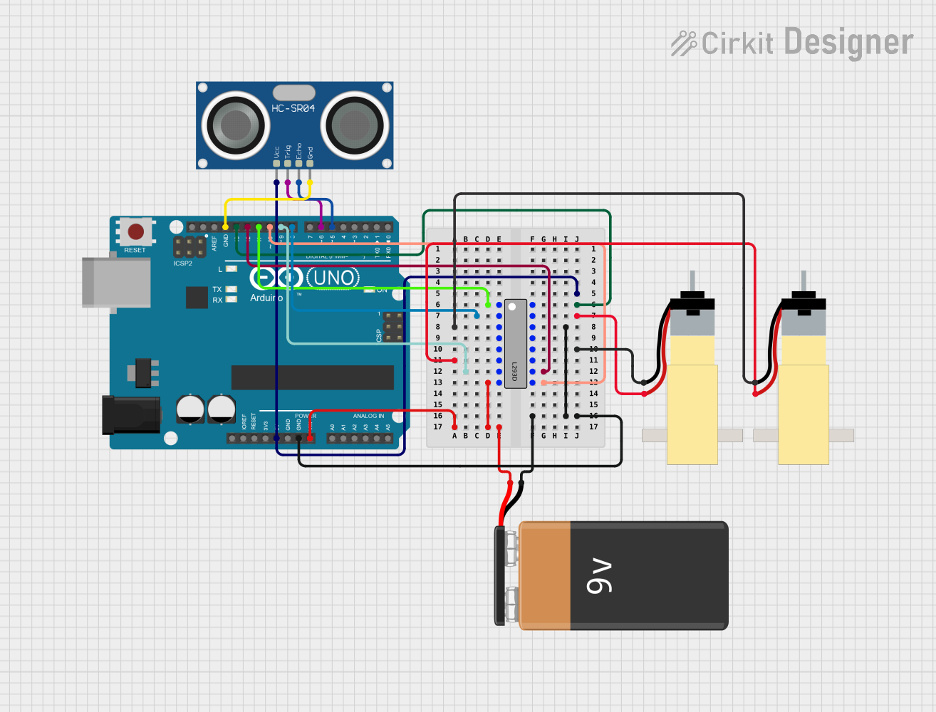
Arduino-Controlled Autonomous Robot with Ultrasonic Obstacle Avoidance

Circuit Documentation
Summary
This circuit is designed to control a small autonomous robot using an Arduino UNO as the central processing unit. The robot utilizes two hobby gearmotors for movement, an HC-SR04 ultrasonic sensor for distance measurement, and an L293D motor driver IC to control the gearmotors. The circuit is powered by a 9V battery, which supplies power to both the Arduino and the motor driver.
Component List
Arduino UNO
- Microcontroller board based on the ATmega328P
- It has 14 digital input/output pins, 6 analog inputs, a 16 MHz quartz crystal, a USB connection, a power jack, an ICSP header, and a reset button.
Hobby Gearmotor with 48:1 Gearbox (x2)
- A small DC motor with a 48:1 gearbox for increased torque.
- It has two pins for electrical connection.
HC-SR04 Ultrasonic Sensor
- An ultrasonic distance sensor capable of measuring distances from 2cm to 400cm.
- It has four pins: VCC, TRIG, ECHO, and GND.
L293D Motor Driver
- A motor driver IC capable of driving two DC motors.
- It has multiple pins for motor control, including Enable, Input, Output, VCC, and GND.
9V Battery
- A standard 9V battery used to provide power to the circuit.
- It has two terminals: positive (+) and negative (-).
Wiring Details
Arduino UNO
- 5V pin connected to the VCC pin of the HC-SR04 Ultrasonic Sensor.
- GND pin connected to the GND pin of the HC-SR04 Ultrasonic Sensor and the GND pin of the L293D.
- Digital pins D5, D6, D8, D9, D10, D11, D12, and D13 are used to interface with the L293D motor driver and the HC-SR04 sensor.
Hobby Gearmotor with 48:1 Gearbox
- One gearmotor's pin 1 connected to the Output 1 of the L293D.
- The same gearmotor's pin 2 connected to the Output 2 of the L293D.
- The other gearmotor's pin 1 connected to the GND of the L293D.
- The other gearmotor's pin 2 connected to the Input 4 of the L293D.
HC-SR04 Ultrasonic Sensor
- VCC pin connected to the 5V output of the Arduino UNO.
- TRIG pin connected to the D6 pin of the Arduino UNO.
- ECHO pin connected to the D5 pin of the Arduino UNO.
- GND pin connected to the GND pin of the Arduino UNO.
L293D Motor Driver
- Enable 1,2 pin connected to the D11 pin of the Arduino UNO.
- Input 1 pin connected to the D8 pin of the Arduino UNO.
- Input 2 pin connected to the D9 pin of the Arduino UNO.
- Input 3 pin connected to the D12 pin of the Arduino UNO.
- Input 4 pin connected to the pin 2 of the second gearmotor.
- Output 1 pin connected to the pin 1 of the first gearmotor.
- Output 2 pin connected to the pin 2 of the first gearmotor.
- Output 4 pin connected to the negative terminal of the 9V Battery.
- GND pin connected to the pin 1 of the second gearmotor.
- VCC1 pin connected to the D13 pin of the Arduino UNO.
- VCC2 pin connected to the positive terminal of the 9V Battery.
- Enable 3,4 pin connected to the D10 pin of the Arduino UNO.
9V Battery
- Positive terminal connected to the VCC2 of the L293D and the Vin of the Arduino UNO.
- Negative terminal connected to the Output 4 of the L293D.
Documented Code
#define Input_1 9  // control pin for motor 1 - input 1 to H-bridge controlling motor 1
#define Input_2 8  // control pin 2 for motor 1 - input 2 to H-bridge controlling motor 1
#define Input_3 13 // control pin 1 for motor 2 - input 1 to H-bridge controlling motor 2
#define Input_4 12 // control pin 2 for motor 2 - input 2 to H-bridge controlling motor 2
#define Enable_1 11 // Power Supply pin 2 for motor 1 - enable 1 to H-bridge powering motor 1
#define Enable_2 10 // Power Supply pin 2 for motor 2 - enable 2 to H-bridge powering motor 1
const int trigPin = 6;
const int echoPin = 5;
long duration;
int distance;

void setup() {
  pinMode(Input_1, OUTPUT);
  pinMode(Input_2, OUTPUT);
  pinMode(Input_3, OUTPUT);
  pinMode(Input_4, OUTPUT);
  pinMode(Enable_1, OUTPUT);
  pinMode(Enable_2, OUTPUT);
  pinMode(trigPin, OUTPUT);
  pinMode(echoPin, INPUT);
  Serial.begin(9600);
}

void goForward() {
  digitalWrite(Enable_1, 100);
  digitalWrite(Enable_2, 100);
  digitalWrite(Input_1, HIGH);
  digitalWrite(Input_2, LOW);
  digitalWrite(Input_3, HIGH);
  digitalWrite(Input_4, LOW);
}

void goBackward() {
  digitalWrite(Enable_1, 100);
  digitalWrite(Enable_2, 100);
  digitalWrite(Input_1, LOW);
  digitalWrite(Input_2, HIGH);
  digitalWrite(Input_3, LOW);
  digitalWrite(Input_4, HIGH);
}

void turnLeft() {
  digitalWrite(Enable_1, 120);
  digitalWrite(Enable_2, 120);
  digitalWrite(Input_1, LOW);
  digitalWrite(Input_2, HIGH);
  digitalWrite(Input_3, HIGH);
  digitalWrite(Input_4, LOW);
}

void stopMoving() {
  digitalWrite(Enable_1, 0);
  digitalWrite(Enable_2, 0);
}

void loop() {
  digitalWrite(Enable_1, HIGH);
  digitalWrite(Enable_2, HIGH);

  digitalWrite(trigPin, LOW);
  delayMicroseconds(2);

  digitalWrite(trigPin, HIGH);
  delayMicroseconds(10);
  digitalWrite(trigPin, LOW);

  duration = pulseIn(echoPin, HIGH);

  distance = duration * 0.034 / 2;

  Serial.print("Distance: ");
  Serial.println(distance);

  if (distance < 40) {
    Serial.println("HEY HEY WAIT A MINUTE MR. POSTMAN!");
    delay(10);
  } else {
    Serial.println("Don't stop me now");
    delay(10);
  }

  if (distance < 30) {
    stopMoving();
    delay(2000);
    goBackward();
    delay(5000);
    turnLeft();
    delay(5000);
  } else {
    goForward();
    delay(10000);
  }
}
This code is designed to control the autonomous robot's movement based on the distance measurements from the HC-SR04 ultrasonic sensor. The robot will move forward continuously until an object is detected within 40 cm. If the object is closer than 30 cm, the robot will stop, move backward, and then turn left before continuing forward. The motor speeds and directions are controlled by the L293D motor driver, which is interfaced with the Arduino UNO.