
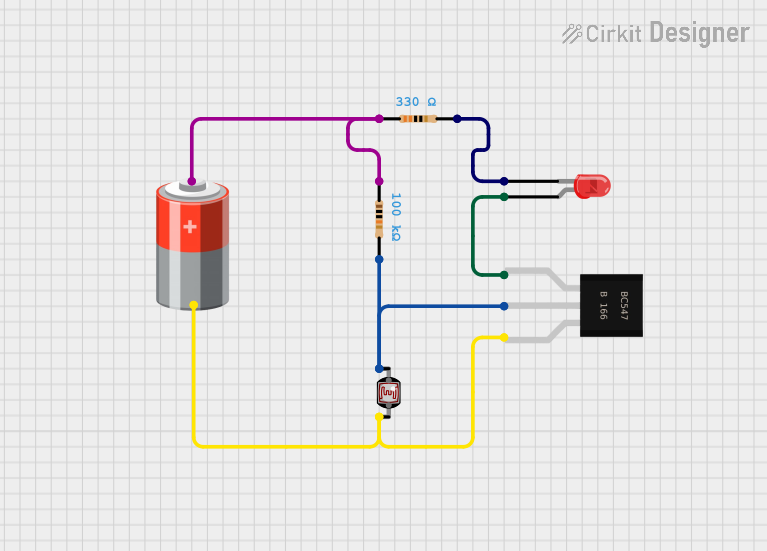
Circuit Documentation
Summary
The circuit described by the provided inputs appears to be a simple light-activated switch using a Light-Dependent Resistor (LDR), a transistor (BC547), a red LED, a 5V battery, and two resistors of different values. The circuit likely functions as a darkness detector, where the LED turns on when the ambient light level falls below a certain threshold. The LDR changes its resistance based on the light intensity, which in turn affects the base current of the transistor, switching the LED on or off.
Component List
LED: Two Pin (red)
- Description: A red light-emitting diode (LED) with two pins: anode and cathode.
- Purpose: To emit light when the circuit is activated.
Resistor (330 Ohms)
- Description: A resistor with a resistance value of 330 Ohms.
- Purpose: To limit the current flowing through the LED, protecting it from damage.
Resistor (100000 Ohms)
- Description: A resistor with a resistance value of 100000 Ohms (100 kOhms).
- Purpose: To form a voltage divider with the LDR, setting the switching threshold for the transistor.
Photocell (LDR)
- Description: A light-dependent resistor whose resistance varies with light intensity.
- Purpose: To sense the ambient light level and control the switching of the transistor.
5v Battery
- Description: A power source providing a constant voltage of 5V.
- Purpose: To power the circuit.
BC547 Transistor
- Description: A general-purpose NPN bipolar junction transistor.
- Purpose: To act as a switch for the LED based on the signal from the LDR and resistor network.
Wiring Details
LED: Two Pin (red)
- Cathode connected to the second pin of a 330 Ohm resistor.
- Anode connected to the collector of the BC547 transistor.
Resistor (330 Ohms)
- Pin1 connected to the positive terminal of the 5V battery and the first pin of the 100 kOhm resistor.
- Pin2 connected to the cathode of the red LED.
Resistor (100000 Ohms)
- Pin1 connected to the positive terminal of the 5V battery and the first pin of the 330 Ohm resistor.
- Pin2 connected to the base of the BC547 transistor and the first pin of the LDR.
Photocell (LDR)
- Pin 0 connected to the second pin of the 100 kOhm resistor and the base of the BC547 transistor.
- Pin 1 connected to the negative terminal of the 5V battery and the emitter of the BC547 transistor.
5v Battery
- + (Positive) connected to the first pin of the 330 Ohm resistor and the first pin of the 100 kOhm resistor.
- - (Negative) connected to the emitter of the BC547 transistor and the second pin of the LDR.
BC547 Transistor
- Collector connected to the anode of the red LED.
- Base connected to the second pin of the 100 kOhm resistor and the first pin of the LDR.
- Emitter connected to the negative terminal of the 5V battery and the second pin of the LDR.
Documented Code
No code has been provided for this circuit as there are no microcontrollers or programmable components involved. The circuit operates purely on the basis of the electronic properties of the components used.