ESP32-Based Power Monitoring System with OLED Display

Circuit Documentation
Summary
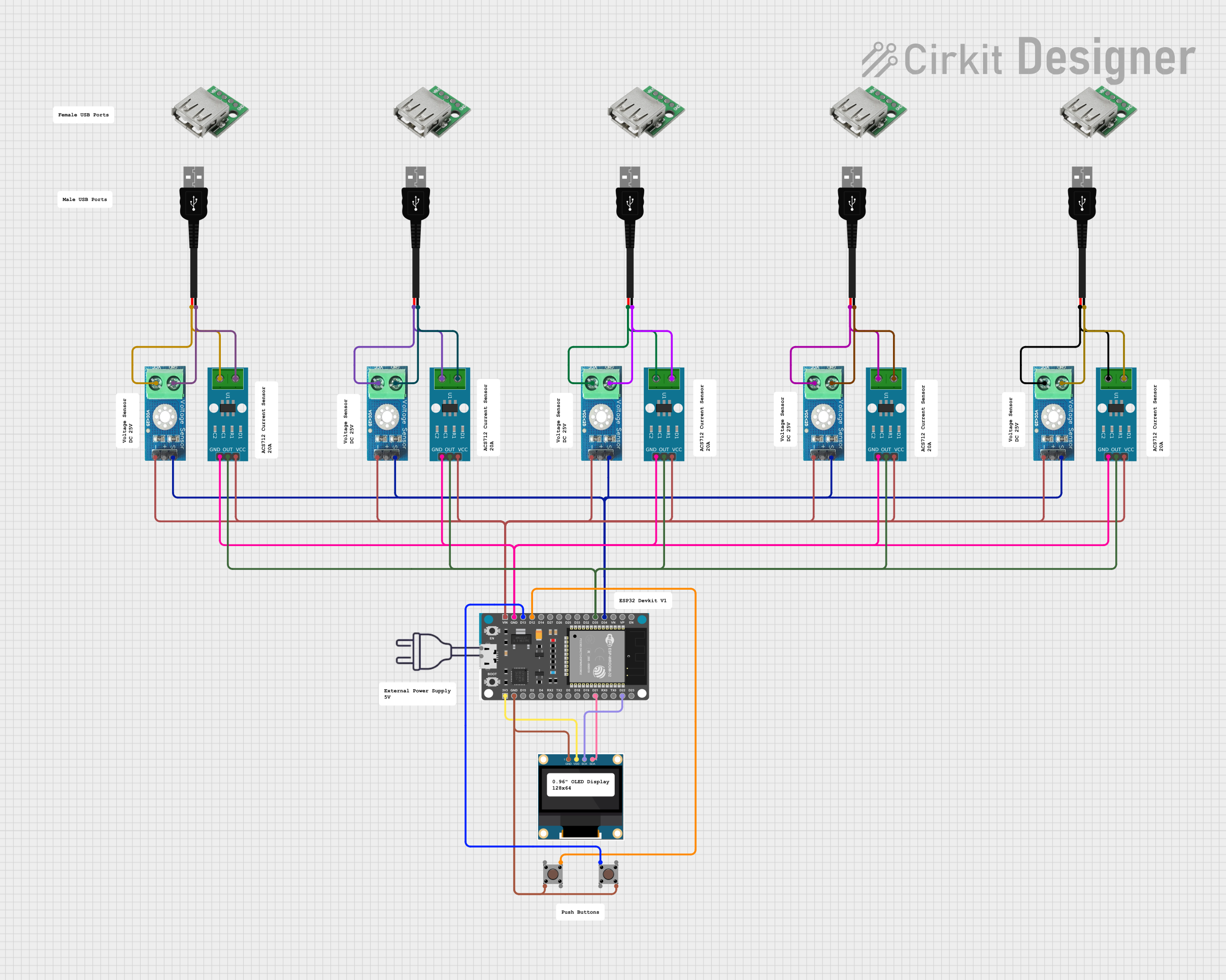
This circuit integrates various sensors, input devices, and a display with an ESP32 Devkit V1 microcontroller. The circuit is designed to measure current using multiple ACS712 Current Sensors and voltage using several Voltage Sensor DC 25V modules. It also includes pushbuttons for user input and a 0.96" OLED display for data output. The ESP32 Devkit V1 serves as the central processing unit, interfacing with the sensors and the display, as well as managing the user input from the pushbuttons. The circuit is powered through USB connections, with power distribution to the sensors and the OLED display.
Component List
Pushbutton
- Description: A simple pushbutton used for user input.
- Pins: Pin 3 (out), Pin 4 (out), Pin 1 (in), Pin 2 (in)
ACS712 Current Sensor 5A 20A 30A
- Description: A current sensor module capable of measuring current flow up to 30A.
- Pins: 1, 2, GND, OUT, VCC
Voltage Sensor DC 25V
- Description: A voltage sensor module for measuring DC voltages up to 25V.
- Pins: +, -, output, gnd, vcc
0.96" OLED
- Description: A small OLED display for showing data.
- Pins: GND, VDD, SCK, SDA
USB male 2 pin connection
- Description: A USB connector for power input.
- Pins: Negative -, Positive +
USB Female
- Description: A USB female port for power output or data communication.
- Pins: VCC, GND, -D, +D
ESP32 Devkit V1
- Description: A microcontroller with Wi-Fi and Bluetooth capabilities.
- Pins: 3V3, GND, D15, D2, D4, RX2, TX2, D5, D18, D19, D21, RX0, TX0, D22, D23, EN, VP, VN, D34, D35, D32, D33, D25, D26, D27, D14, D12, D13, VIN
power 220v
- Description: A power source for the circuit.
- Pins: hot wire, neutral wire
Wiring Details
Pushbutton
- Pin 2 (in) and Pin 4 (out) are connected to GND.
- Pin 3 (out) is connected to ESP32 Devkit V1 Pin D12.
- Pin 1 (in) is connected to ESP32 Devkit V1 Pin D13.
ACS712 Current Sensor 5A 20A 30A
- OUT pins are connected to ESP32 Devkit V1 Pin D35.
- GND pins are connected to GND.
- VCC pins are connected to ESP32 Devkit V1 VIN.
- Pin 1 is connected to USB male 2 pin connection Negative -.
- Pin 2 is connected to USB male 2 pin connection Positive +.
Voltage Sensor DC 25V
- output pins are connected to ESP32 Devkit V1 Pin D34.
- pins are connected to GND.
- vcc pins are connected to ESP32 Devkit V1 VIN.
- gnd pins are connected to USB male 2 pin connection Negative -.
0.96" OLED
- GND is connected to GND.
- VDD is connected to ESP32 Devkit V1 3V3.
- SCK is connected to ESP32 Devkit V1 Pin D22.
- SDA is connected to ESP32 Devkit V1 Pin D21.
USB male 2 pin connection
- Negative - is connected to GND.
- Positive + is connected to ESP32 Devkit V1 VIN.
USB Female
- VCC is connected to ESP32 Devkit V1 VIN.
- GND is connected to GND.
ESP32 Devkit V1
- 3V3 is connected to 0.96" OLED VDD.
- GND is connected to various components as a common ground.
- D21 is connected to 0.96" OLED SDA.
- D22 is connected to 0.96" OLED SCK.
- D34 is connected to Voltage Sensor DC 25V output.
- D35 is connected to ACS712 Current Sensor OUT.
- VIN is connected to USB male 2 pin connection Positive + and powers the ACS712 Current Sensors and Voltage Sensors.
Documented Code
There is no code provided for the microcontroller. The documentation of the code would typically include details on how the ESP32 Devkit V1 is programmed to interact with the sensors, display, and pushbuttons, including any libraries used, the main loop, and functions for reading sensor data and updating the display. However, since no code has been provided, this section cannot be completed.