
Arduino Mega 2560 Controlled Security Access System with RFID and Keypad
View and Edit Project In Cirkit Designer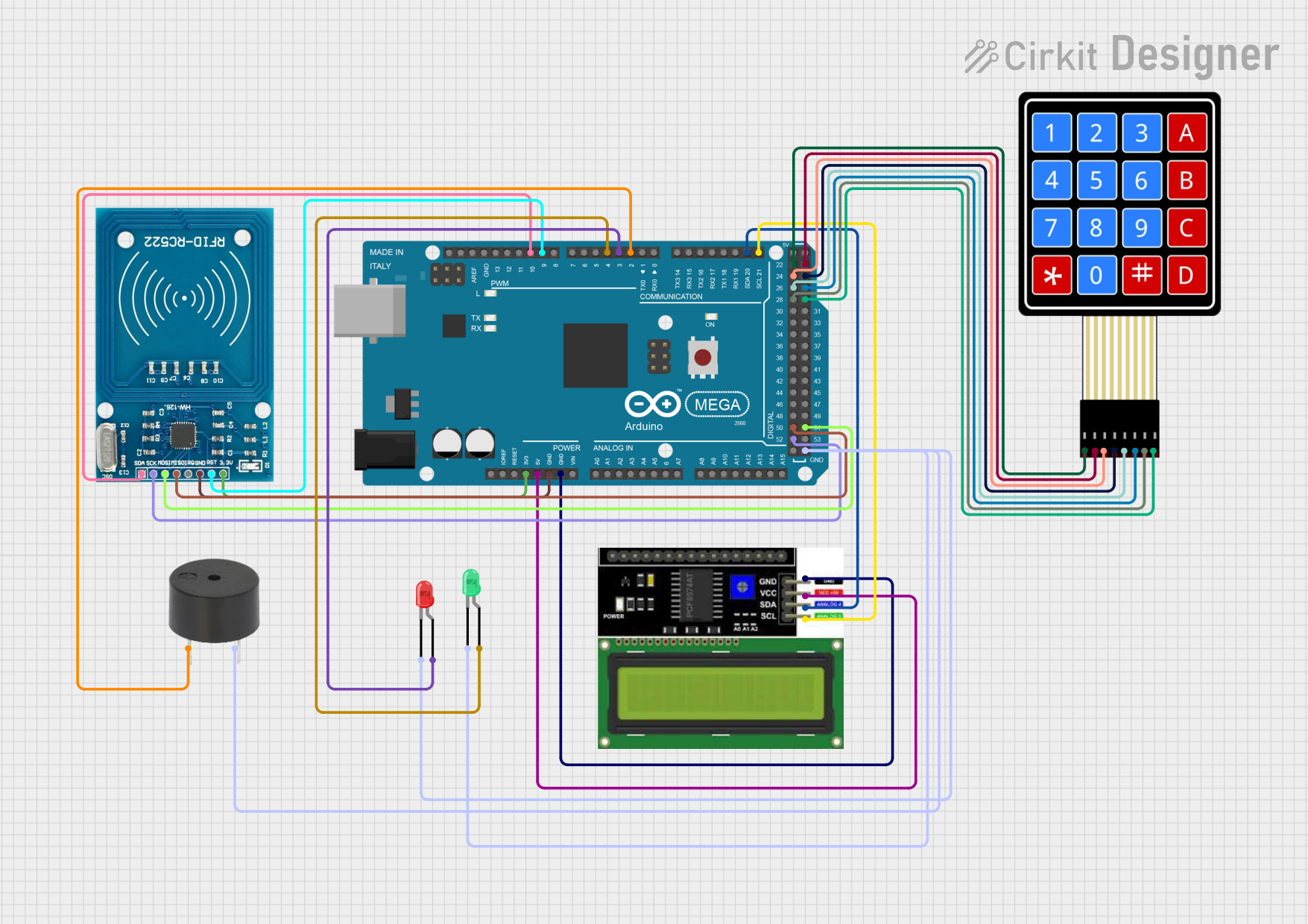
Circuit Documentation
Summary
This circuit is designed to interface various components with an Arduino Mega 2560 microcontroller. The components include a red LED, a green LED, a buzzer, a 4x4 membrane matrix keypad, an LCD I2C display, and an RFID-RC522 module. The circuit is likely intended for a user interface system with visual indicators (LEDs), audible feedback (buzzer), input capability (keypad), data display (LCD), and RFID functionality for identification or security purposes.
Component List
LED: Two Pin (red)
- Description: A red light-emitting diode (LED) used as a visual indicator.
- Pins: cathode, anode
LED: Two Pin (green)
- Description: A green light-emitting diode (LED) used as a visual indicator.
- Pins: cathode, anode
Buzzer
- Description: An audible signaling device.
- Pins: PIN, GND
4X4 Membrane Matrix Keypad
- Description: An input device with 16 buttons arranged in a 4x4 matrix.
- Pins: R1, R2, R3, R4, C1, C2, C3, C4
LCD I2C Display
- Description: A liquid crystal display with an I2C interface for showing data.
- Pins: GND, VCC, SDA, SCL
RFID-RC522
- Description: An RFID reader/writer module for contactless communication using radio frequency.
- Pins: VCC (3.3V), RST, GND, IRQ, MISO, MOSI, SCK, SDA
Arduino Mega 2560
- Description: A microcontroller board based on the ATmega2560 with numerous digital and analog I/O pins.
- Pins: Multiple digital and analog pins, power supply pins, and communication interface pins.
Wiring Details
LED: Two Pin (red)
- Cathode: Connected to GND of Arduino Mega 2560
- Anode: Connected to pin D3 PWM of Arduino Mega 2560
LED: Two Pin (green)
- Cathode: Connected to GND of Arduino Mega 2560
- Anode: Connected to pin D4 PWM of Arduino Mega 2560
Buzzer
- PIN: Connected to pin D2 PWM of Arduino Mega 2560
- GND: Connected to GND of Arduino Mega 2560
4X4 Membrane Matrix Keypad
- R1: Connected to pin D22 of Arduino Mega 2560
- R2: Connected to pin D23 of Arduino Mega 2560
- R3: Connected to pin D24 of Arduino Mega 2560
- R4: Connected to pin D25 of Arduino Mega 2560
- C1: Connected to pin D26 of Arduino Mega 2560
- C2: Connected to pin D27 of Arduino Mega 2560
- C3: Connected to pin D28 of Arduino Mega 2560
- C4: Connected to pin D29 of Arduino Mega 2560
LCD I2C Display
- GND: Connected to GND of Arduino Mega 2560
- VCC: Connected to 5V of Arduino Mega 2560
- SDA: Connected to pin D20/SDA of Arduino Mega 2560
- SCL: Connected to pin D21/SCL of Arduino Mega 2560
RFID-RC522
- VCC (3.3V): Connected to 3V3 of Arduino Mega 2560
- RST: Connected to pin D9 PWM of Arduino Mega 2560
- GND: Connected to GND of Arduino Mega 2560
- MISO: Connected to pin D50 of Arduino Mega 2560
- MOSI: Connected to pin D51 of Arduino Mega 2560
- SCK: Connected to pin D52 of Arduino Mega 2560
- SDA: Connected to pin D10 PWM of Arduino Mega 2560
Documented Code
void setup() {
  // put your setup code here, to run once:

}

void loop() {
  // put your main code here, to run repeatedly:

}
The provided code is a template with empty setup() and loop() functions, which are the standard structure for Arduino sketches. The setup() function is intended to contain initialization code that runs once when the microcontroller is powered on or reset. The loop() function is for code that runs continuously as long as the microcontroller is powered. Specific functionality must be added to these functions to control the components in the circuit.