Arduino UNO Controlled Traffic Light System
Traffic Light Control Circuit Documentation
Summary
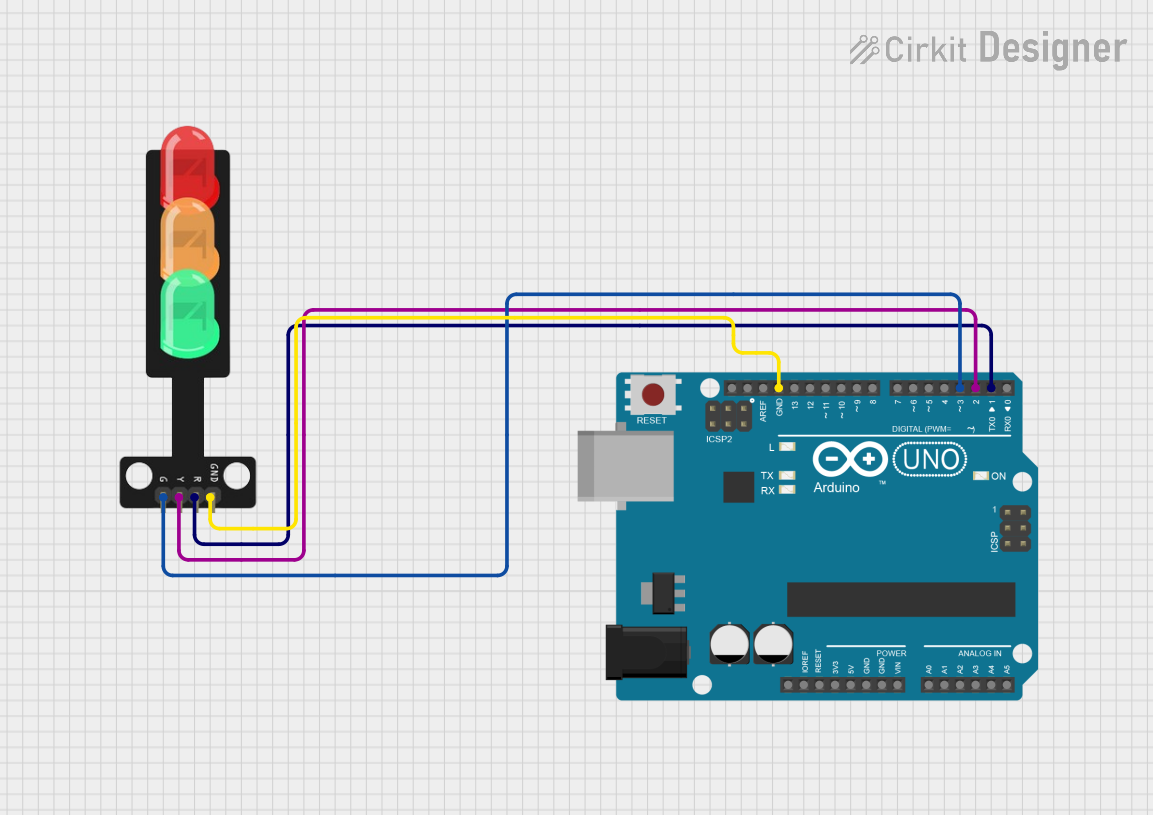
This circuit is designed to control a traffic light system using an Arduino UNO microcontroller. The system operates a simple traffic light sequence that cycles through green, yellow, and red LEDs. The sequence is programmed to turn on the green LED for 5 seconds, followed by the yellow LED for 2 seconds, and then the red LED for 5 seconds. This cycle repeats indefinitely to simulate a traffic light operation.
Component List
Arduino UNO
- Description: A microcontroller board based on the ATmega328P.
- Purpose: Acts as the control unit for the traffic light system, driving the LEDs based on the programmed sequence.
- Pins: UNUSED, IOREF, Reset, 3.3V, 5V, GND, Vin, A0-A5, SCL, SDA, AREF, D0-D13
Traffic Light
- Description: A simple traffic light module with three LEDs (Green, Yellow, Red).
- Purpose: Represents the traffic light, displaying the current state of the traffic signal.
- Pins: Green, Yellow, Red, GND
Wiring Details
Arduino UNO
- GND connected to Traffic Light GND
- D3 connected to Traffic Light Green LED
- D2 connected to Traffic Light Yellow LED
- D1 connected to Traffic Light Red LED
Traffic Light
- Green connected to Arduino UNO D3
- Yellow connected to Arduino UNO D2
- Red connected to Arduino UNO D1
- GND connected to Arduino UNO GND
Documented Code
/*
 * This Arduino sketch controls a traffic light system.
 * The sequence is as follows:
 * - Green LED on for 5 seconds
 * - Yellow LED on for 2 seconds
 * - Red LED on for 5 seconds
 * This sequence repeats indefinitely.
 */

// Pin definitions
const int redPin = 1;    // Connect to the Red LED of the Traffic Light
const int yellowPin = 2; // Connect to the Yellow LED of the Traffic Light
const int greenPin = 3;  // Connect to the Green LED of the Traffic Light

void setup() {
  // Initialize the digital pins as outputs
  pinMode(redPin, OUTPUT);
  pinMode(yellowPin, OUTPUT);
  pinMode(greenPin, OUTPUT);
}

void loop() {
  // Green LED on for 5 seconds
  digitalWrite(greenPin, HIGH);
  delay(5000);
  digitalWrite(greenPin, LOW);

  // Yellow LED on for 2 seconds
  digitalWrite(yellowPin, HIGH);
  delay(2000);
  digitalWrite(yellowPin, LOW);

  // Red LED on for 5 seconds
  digitalWrite(redPin, HIGH);
  delay(5000);
  digitalWrite(redPin, LOW);
}
Filename: sketch.ino
This code is written for the Arduino UNO microcontroller to control the traffic light sequence. The setup() function initializes the digital pins connected to the LEDs as outputs. The loop() function contains the logic to turn on and off each LED in the sequence described in the summary. The delay() function is used to keep each LED on for the specified duration.