
Circuit Documentation
Summary
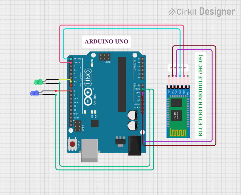
This circuit involves an Arduino UNO microcontroller, an HC-05 Bluetooth module, and two LEDs (one blue and one green). The Arduino UNO is used to control the LEDs based on commands received via Bluetooth from the HC-05 module. The blue LED is connected to digital pin 7, and the green LED is connected to digital pin 6 of the Arduino. The HC-05 module communicates with the Arduino via serial communication.
Component List
HC-05 Bluetooth Module
- Description: A Bluetooth module used for wireless communication.
- Pins: Key, VCC, GND, TXD, RXD, State
Arduino UNO
- Description: A microcontroller board based on the ATmega328P.
- Pins: UNUSED, IOREF, Reset, 3.3V, 5V, GND, Vin, A0, A1, A2, A3, A4, A5, SCL, SDA, AREF, D13, D12, D11, D10, D9, D8, D7, D6, D5, D4, D3, D2, D1, D0
LED: Two Pin (blue)
- Description: A blue LED.
- Pins: Cathode, Anode
LED: Two Pin (green)
- Description: A green LED.
- Pins: Cathode, Anode
Wiring Details
HC-05 Bluetooth Module
- VCC: Connected to Arduino UNO 5V
- GND: Connected to Arduino UNO GND
- TXD: Connected to Arduino UNO D0
- RXD: Connected to Arduino UNO D1
Arduino UNO
- 5V: Connected to HC-05 Bluetooth Module VCC
- GND: Connected to HC-05 Bluetooth Module GND, Blue LED Cathode, Green LED Cathode
- D7: Connected to Blue LED Anode
- D6: Connected to Green LED Anode
- D0: Connected to HC-05 Bluetooth Module TXD
- D1: Connected to HC-05 Bluetooth Module RXD
LED: Two Pin (blue)
- Cathode: Connected to Arduino UNO GND
- Anode: Connected to Arduino UNO D7
LED: Two Pin (green)
- Cathode: Connected to Arduino UNO GND
- Anode: Connected to Arduino UNO D6
Code Documentation
char BluetoothData;
int LED1 = 7;
int LED2 = 6;

void setup()
{
    pinMode(LED1, OUTPUT);
    pinMode(LED2, OUTPUT);
    Serial.begin(9600);
}

void loop()
{
    if (Serial.available())
    {
        BluetoothData = Serial.read();
        Serial.println(BluetoothData);
    }

    // CONTROL LED1
    if (BluetoothData == '1')
    {
        digitalWrite(LED1, 1);
    }

    if (BluetoothData == '2')
    {
        digitalWrite(LED1, 0);
    }

    // CONTROL LED2
    if (BluetoothData == '3')
    {
        digitalWrite(LED2, 1);
    }

    if (BluetoothData == '4')
    {
        digitalWrite(LED2, 0);
    }

    // CONTROL ALL LEDS
    if (BluetoothData == '5')
    {
        digitalWrite(LED1, 1);
        digitalWrite(LED2, 1);
    }

    if (BluetoothData == '6')
    {
        digitalWrite(LED1, 0);
        digitalWrite(LED2, 0);
    }
}
This code initializes the pins connected to the LEDs as output and sets up serial communication at a baud rate of 9600. In the main loop, it reads data from the Bluetooth module and controls the LEDs based on the received commands.