
ESP32-S3 Controlled Motor Driver System with DC Step-Down Buck Converter
View and Edit Project In Cirkit Designer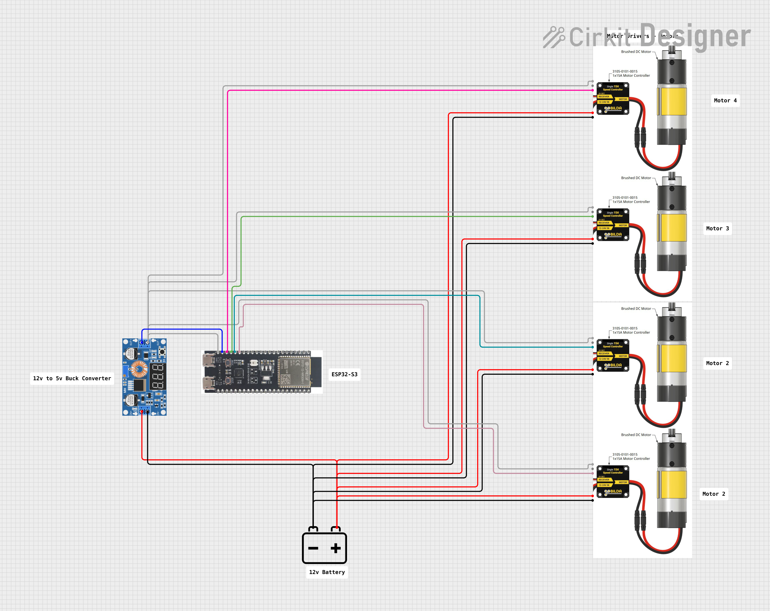
Circuit Documentation
Summary of the Circuit
The circuit described by the provided inputs consists of a power regulation system, a microcontroller, and multiple motor controllers. The power regulation is achieved using an XL4015 5A DC Buck Step-down module that steps down the voltage from a 12v Battery to a lower voltage suitable for the microcontroller and motor controllers. The ESP32-S3 microcontroller is used to control the motor controllers through GPIO pins. Each motor controller is capable of driving a motor and receives control signals from the ESP32-S3.
Component List
XL4015 5A DC Buck Step-down
- Description: A DC-DC step-down (buck) converter module capable of handling up to 5A of current.
- Pins: Output +, Output -, Input +, Input -
12v Battery
- Description: A 12-volt battery providing the primary power source for the circuit.
- Pins: +, -
1x15A Motor Controllers
- Description: Motor controller modules capable of driving motors with up to 15A of current.
- Pins: 12v GND, 12v+, SIG, 6v+, 6v/SIG GND
ESP32-S3
- Description: A microcontroller with Wi-Fi and Bluetooth capabilities and a variety of GPIO pins for interfacing with other components.
- Pins: 3v3, EN, GPIO4, GPIO5, GPIO6, GPIO7, GPIO15, GPIO16, GPIO17, GPIO18, GPIO8, GPIO46, GPIO9, GPIO10, GPIO11, GPIO12, GPIO13, GPIO14, 5V, GND, GPIO43, GPIO44, GPIO1, GPIO2, GPIO42, GPIO41, GPIO40, GPIO39, GPIO38, GPIO37, GPIO36, GPIO35, GPIO0, GPIO45, GPIO48, GPIO47, GPIO21, GPIO20, GPIO19
Comments
- Description: Comments are placeholders for notes or annotations within the circuit design. They do not have electrical function.
Wiring Details
XL4015 5A DC Buck Step-down
- Output +: Connected to the 5V pin of the ESP32-S3.
- Output -: Connected to the 6v/SIG GND pins of all 1x15A Motor Controllers and the GND pin of the ESP32-S3.
- Input +: Connected to the 12v+ pins of all 1x15A Motor Controllers and the + pin of the 12v Battery.
- Input -: Connected to the 12v GND pins of all 1x15A Motor Controllers and the - pin of the 12v Battery.
12v Battery
- +: Connected to the Input + of the XL4015 5A DC Buck Step-down and the 12v+ pins of all 1x15A Motor Controllers.
- -: Connected to the Input - of the XL4015 5A DC Buck Step-down and the 12v GND pins of all 1x15A Motor Controllers.
1x15A Motor Controllers
- 12v GND: Connected to the Input - of the XL4015 5A DC Buck Step-down and the - pin of the 12v Battery.
- 12v+: Connected to the Input + of the XL4015 5A DC Buck Step-down and the + pin of the 12v Battery.
- SIG: Each SIG pin is connected to a unique GPIO pin on the ESP32-S3 (GPIO11, GPIO12, GPIO13, GPIO14).
- 6v+: Not connected in the provided net list.
- 6v/SIG GND: Connected to the Output - of the XL4015 5A DC Buck Step-down and the GND pin of the ESP32-S3.
ESP32-S3
- 5V: Connected to the Output + of the XL4015 5A DC Buck Step-down.
- GND: Connected to the Output - of the XL4015 5A DC Buck Step-down.
- GPIO11, GPIO12, GPIO13, GPIO14: Each connected to the SIG pin of a unique 1x15A Motor Controller.
Documented Code
No code was provided for the microcontroller. Typically, this section would include the embedded code for the ESP32-S3, detailing how it interfaces with the motor controllers and any other peripherals. The code would be responsible for initializing the GPIO pins, setting up communication protocols, and implementing the control logic for the motors. Since no code is available, this section remains empty.