
ESP8266 NodeMCU Controlled Environmental Monitoring System with OLED Display and Relay Switching
View and Edit Project In Cirkit Designer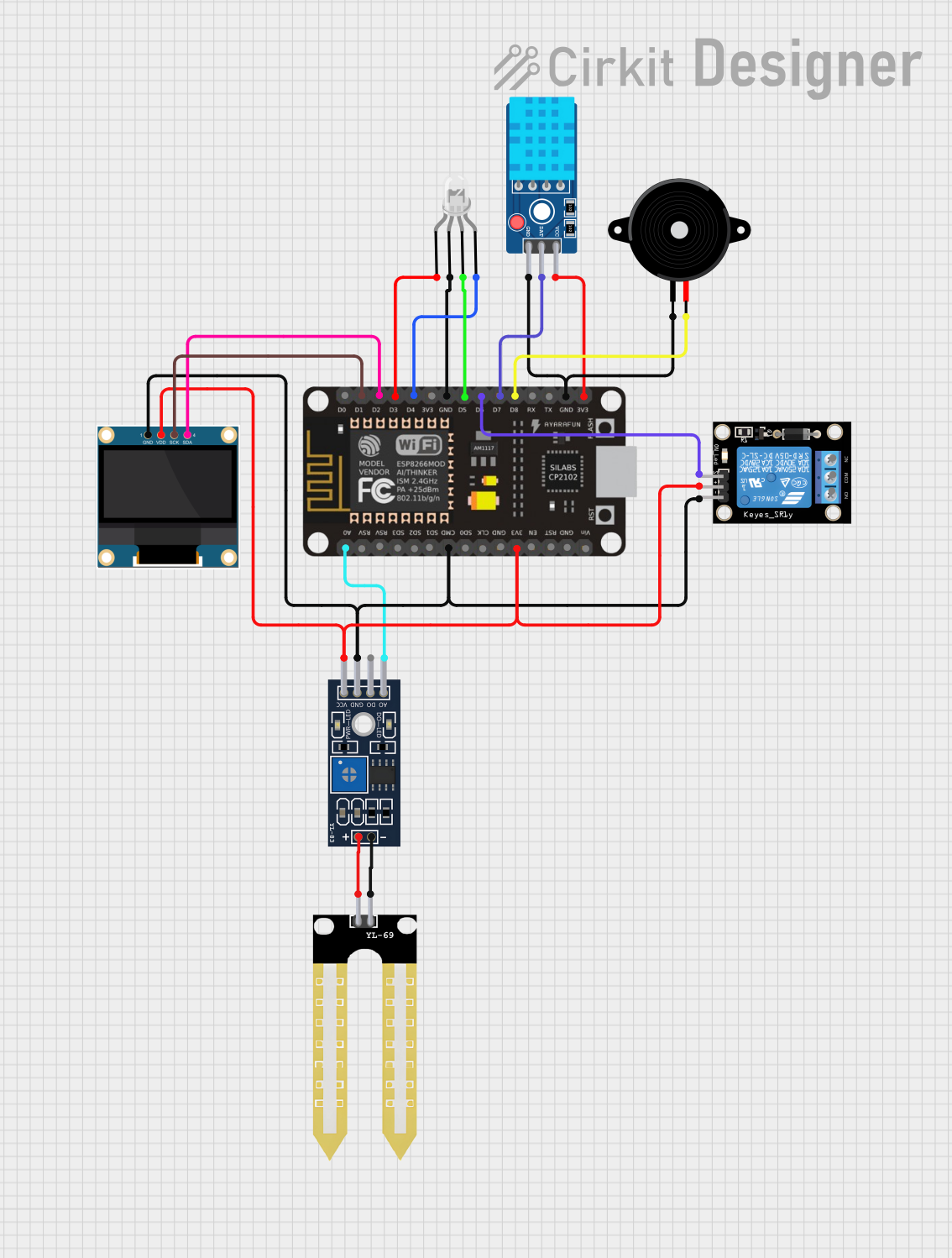
Circuit Documentation
Summary of the Circuit
This circuit is designed to interface an ESP8266 NodeMCU microcontroller with a variety of sensors, actuators, and display modules. The components include a DHT11 temperature and humidity sensor, a YL-83 rain sensor module with a YL-69 probe, a common cathode RGB LED, a 0.96" OLED display, a piezo speaker, and a KY-019 relay module. The ESP8266 NodeMCU serves as the central processing unit, reading sensor data, controlling the LED and relay, and displaying information on the OLED screen. The circuit is powered by the 3V3 output from the ESP8266 NodeMCU, which is also used to power the sensors and the OLED display.
Component List
ESP8266 NodeMCU
- Microcontroller module with WiFi capability.
- Provides GPIO pins for interfacing with other components.
DHT11 Sensor V2
- Temperature and humidity sensor.
- Outputs sensor data to a digital pin.
YL-83 Module LM393
- Rain sensor module that provides both analog and digital outputs.
- Works in conjunction with the YL-69 probe.
YL-69 Sonda
- Probe that detects water levels for the YL-83 module.
LED: Four Pin (Common Cathode)
- RGB LED with a common cathode.
- Allows for color mixing by controlling the individual anodes.
0.96" OLED
- Small display for showing text and graphics.
- Communicates via I2C protocol.
Piezo Speaker
- Simple audio output device.
- Can be used to generate tones.
KY-019 Relay module 1 channel
- Single-channel relay module for controlling high-power devices.
- Has Normally Open (NO) and Normally Closed (NC) connections.
Wiring Details
ESP8266 NodeMCU
D1connected to OLEDSCKD2connected to OLEDSDAD3connected to LEDred anodeD4connected to LEDblue anodeD5connected to LEDgreen anodeD6connected to RelaySD7connected to DHT11DATD8connected to Piezo Speakerpin2GNDconnected to LEDcommon cathode, Piezo Speakerpin1, DHT11GND, RelayGND, OLEDGND, and YL-83GND3V3connected to DHT11VCC, Relay5V, OLEDVDD, and YL-83VCCA0connected to YL-83A0
DHT11 Sensor V2
DATconnected to ESP8266 NodeMCUD7GNDconnected to ESP8266 NodeMCUGNDVCCconnected to ESP8266 NodeMCU3V3
YL-83 Module LM393
A0connected to ESP8266 NodeMCUA0D0not connectedGNDconnected to ESP8266 NodeMCUGNDVCCconnected to ESP8266 NodeMCU3V3-connected to YL-69 Sonda-+connected to YL-69 Sonda+
YL-69 Sonda
-connected to YL-83-+connected to YL-83+
LED: Four Pin (Common Cathode)
red anodeconnected to ESP8266 NodeMCUD3common cathodeconnected to ESP8266 NodeMCUGNDgreen anodeconnected to ESP8266 NodeMCUD5blue anodeconnected to ESP8266 NodeMCUD4
0.96" OLED
GNDconnected to ESP8266 NodeMCUGNDVDDconnected to ESP8266 NodeMCU3V3SCKconnected to ESP8266 NodeMCUD1SDAconnected to ESP8266 NodeMCUD2
Piezo Speaker
pin1connected to ESP8266 NodeMCUGNDpin2connected to ESP8266 NodeMCUD8
KY-019 Relay module 1 channel
Sconnected to ESP8266 NodeMCUD65Vconnected to ESP8266 NodeMCU3V3GNDconnected to ESP8266 NodeMCUGNDNC,COM,NOnot connected in this documentation
Documented Code
No code was provided for the microcontrollers in the circuit. To fully utilize the hardware, embedded code would need to be written to handle sensor data acquisition, control the RGB LED, drive the OLED display, generate audio signals with the piezo speaker, and manage the relay operations based on the logic defined for the application.