
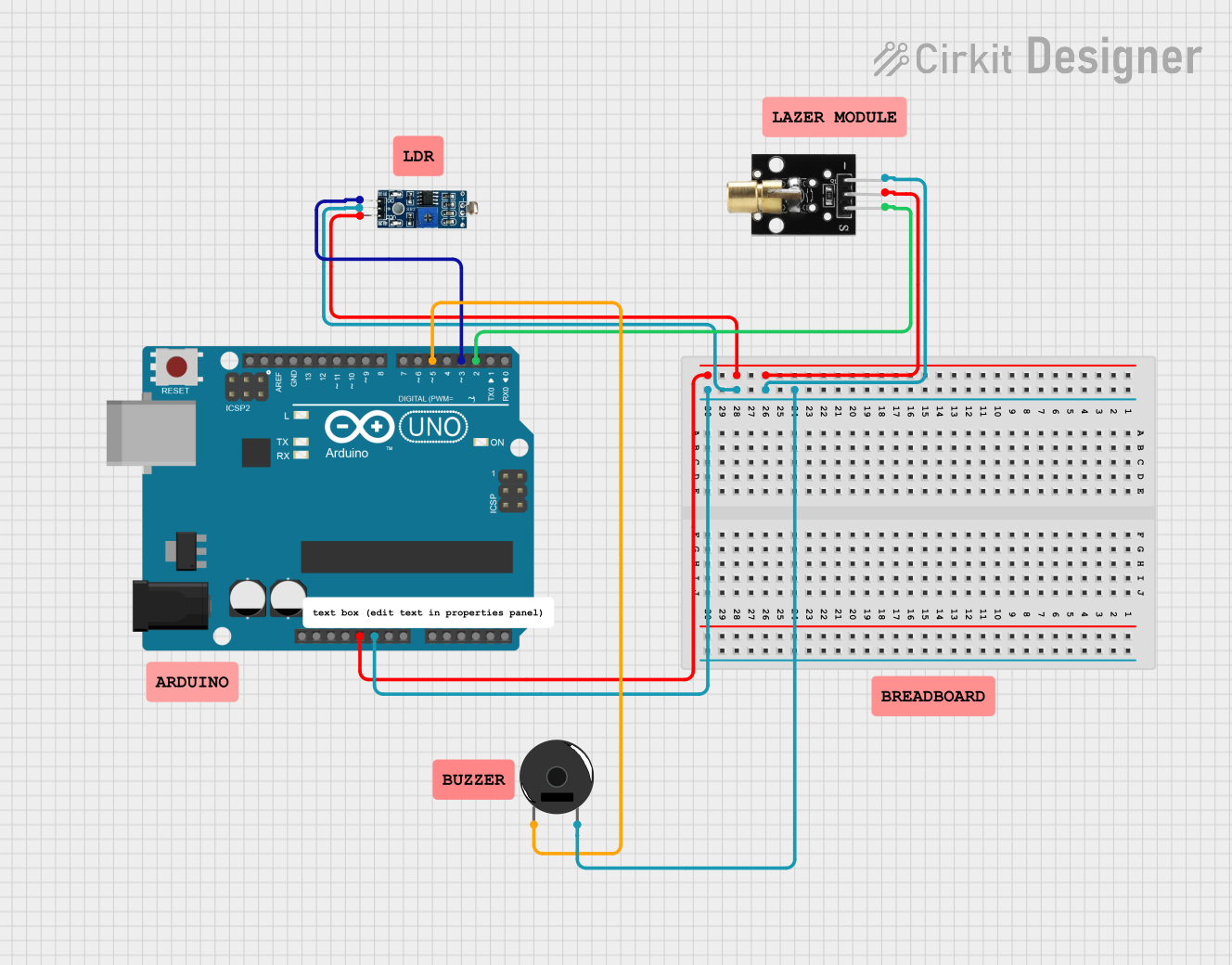
Laser Alarm System Documentation
Summary
This document provides a detailed overview of a laser alarm system. The system uses an Arduino UNO microcontroller, a KY-008 Laser Emitter, an LDR Module, and a Piezo Buzzer. The laser module emits a beam that is detected by the LDR. If the beam is interrupted, the buzzer sounds an alarm.
Component List
Arduino UNO
- Description: A microcontroller board based on the ATmega328P.
- Pins: UNUSED, IOREF, Reset, 3.3V, 5V, GND, Vin, A0, A1, A2, A3, A4, A5, SCL, SDA, AREF, D13, D12, D11, D10, D9, D8, D7, D6, D5, D4, D3, D2, D1, D0
Piezo Buzzer
- Description: An electronic device that produces a sound when a voltage is applied.
- Pins: pin 1, pin 2
KY-008 Laser Emitter
- Description: A laser module that emits a red laser beam.
- Pins: SIG, 5v, GND
LDR Module 3 pin
- Description: A light-dependent resistor module that changes its resistance based on the light intensity.
- Pins: VCC, GND, DO
Wiring Details
Arduino UNO
- GND: Connected to GND of Piezo Buzzer, KY-008 Laser Emitter, and LDR Module.
- 5V: Connected to 5v of KY-008 Laser Emitter and VCC of LDR Module.
- D5: Connected to pin 1 of Piezo Buzzer.
- D3: Connected to DO of LDR Module.
- D2: Connected to SIG of KY-008 Laser Emitter.
Piezo Buzzer
- pin 1: Connected to D5 of Arduino UNO.
- pin 2: Connected to GND of Arduino UNO.
KY-008 Laser Emitter
- SIG: Connected to D2 of Arduino UNO.
- 5v: Connected to 5V of Arduino UNO.
- GND: Connected to GND of Arduino UNO.
LDR Module 3 pin
- VCC: Connected to 5V of Arduino UNO.
- GND: Connected to GND of Arduino UNO.
- DO: Connected to D3 of Arduino UNO.
Code
/*
 * Laser Alarm System
 * Components:
 * - Arduino UNO
 * - KY-008 Laser Emitter
 * - LDR Module 3 pin
 * - Piezo Buzzer
 *
 * Description:
 * This system uses a laser module and an LDR to detect if the laser beam is
 * interrupted. If the beam is interrupted, the buzzer will sound an alarm.
 */

#define LASER_PIN 2
#define SENSOR_PIN 3
#define BUZZER_PIN 5

void setup() {
  Serial.begin(9600);
  pinMode(LASER_PIN, OUTPUT);
  pinMode(SENSOR_PIN, INPUT);
  pinMode(BUZZER_PIN, OUTPUT);

  digitalWrite(LASER_PIN, HIGH); // Turn on the laser
}

void loop() {
  int sensorValue = digitalRead(SENSOR_PIN);

  if (sensorValue == LOW) {
    digitalWrite(BUZZER_PIN, HIGH); // Sound the alarm
  } else {
    digitalWrite(BUZZER_PIN, LOW); // Turn off the alarm
  }
}
This code initializes the laser, sensor, and buzzer pins. The laser is turned on in the setup function. In the loop function, the sensor value is read continuously. If the sensor value is LOW (indicating the laser beam is interrupted), the buzzer is turned on. Otherwise, the buzzer is turned off.