Wemos D1 Mini Controlled Relay with IR Sensor and LED Indicator
Circuit Documentation
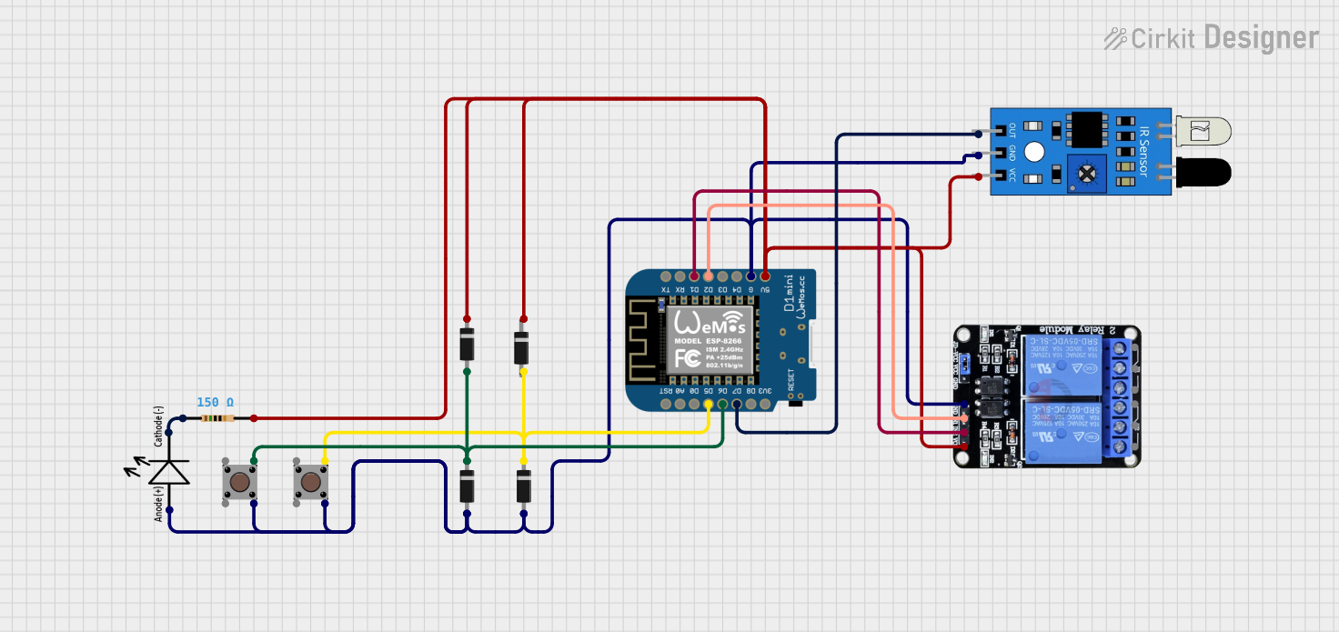
Summary of the Circuit
This circuit is designed to interface a Wemos D1 Mini microcontroller with a two-channel relay module, an infrared (IR) sensor, a set of diodes, pushbuttons, an LED, and a resistor. The Wemos D1 Mini controls the relay module and reads the state of the IR sensor. The pushbuttons and diodes are used to provide input signals to the microcontroller, while the LED indicates the status or output of the circuit. The resistor is used to limit the current through the LED.
Component List
Wemos D1 Mini
- Microcontroller board based on the ESP8266.
- Pins: RST, A0, D0, D5, D6, D7, D8, 3V3, 5V, G, D4, D3, D2, D1, RX, TX.
Two Channel Relay 5v
- Relay module with two channels.
- Pins: VCC, IN2, IN1, GND, NC2, C2, NO2, NC1, C1, NO1.
IR Sensor
- Sensor for detecting infrared signals.
- Pins: out, gnd, vcc.
Diodes (4x)
- Semiconductor devices that allow current to flow in one direction.
- Pins: cathode, anode.
Pushbuttons (2x)
- Simple switches to provide a user interface.
- Pins: Pin 3 (out), Pin 4 (out), Pin 1 (in), Pin 2 (in).
LED
- Light Emitting Diode used as an indicator.
- Pins: -, +.
Resistor
- Passive component used to limit current.
- Resistance: 150 Ohms.
Wiring Details
Wemos D1 Mini
- D5 connected to Diode (cathode) and Pushbutton (Pin 3 out).
- D6 connected to Diode (cathode) and Pushbutton (Pin 3 out).
- D7 connected to IR Sensor (out).
- 5V connected to Diode (cathode), IR Sensor (vcc), and Relay Module (VCC).
- G connected to Diode (anode), Pushbutton (Pin 4 out), IR Sensor (gnd), and Relay Module (GND).
- D2 connected to Relay Module (IN1).
- D1 connected to Relay Module (IN2).
Two Channel Relay 5v
- VCC connected to Wemos D1 Mini (5V).
- IN1 connected to Wemos D1 Mini (D2).
- IN2 connected to Wemos D1 Mini (D1).
- GND connected to Wemos D1 Mini (G).
IR Sensor
- out connected to Wemos D1 Mini (D7).
- gnd connected to Wemos D1 Mini (G).
- vcc connected to Wemos D1 Mini (5V).
Diodes
- Diode anodes connected to Wemos D1 Mini (G).
- Diode cathodes connected to Wemos D1 Mini (D5, D6) and Relay Module (VCC).
Pushbuttons
- Pin 3 (out) connected to Wemos D1 Mini (D5, D6).
- Pin 4 (out) connected to Wemos D1 Mini (G).
LED
- connected to Wemos D1 Mini (G).
- connected to Resistor (pin1).
Resistor
- pin1 connected to LED (-).
- pin2 connected to Diode (cathode) and Relay Module (VCC).
Documented Code
No code has been provided for the microcontroller. The documentation of the code would typically include a description of the functionality implemented in the code, such as reading sensor inputs, controlling relay states, and managing LED status based on certain conditions. Since no code is available, this section cannot be completed.