Arduino Mega 2560 Controlled AC Dimmer Lamp with Voltage Monitoring
Circuit Documentation
Summary
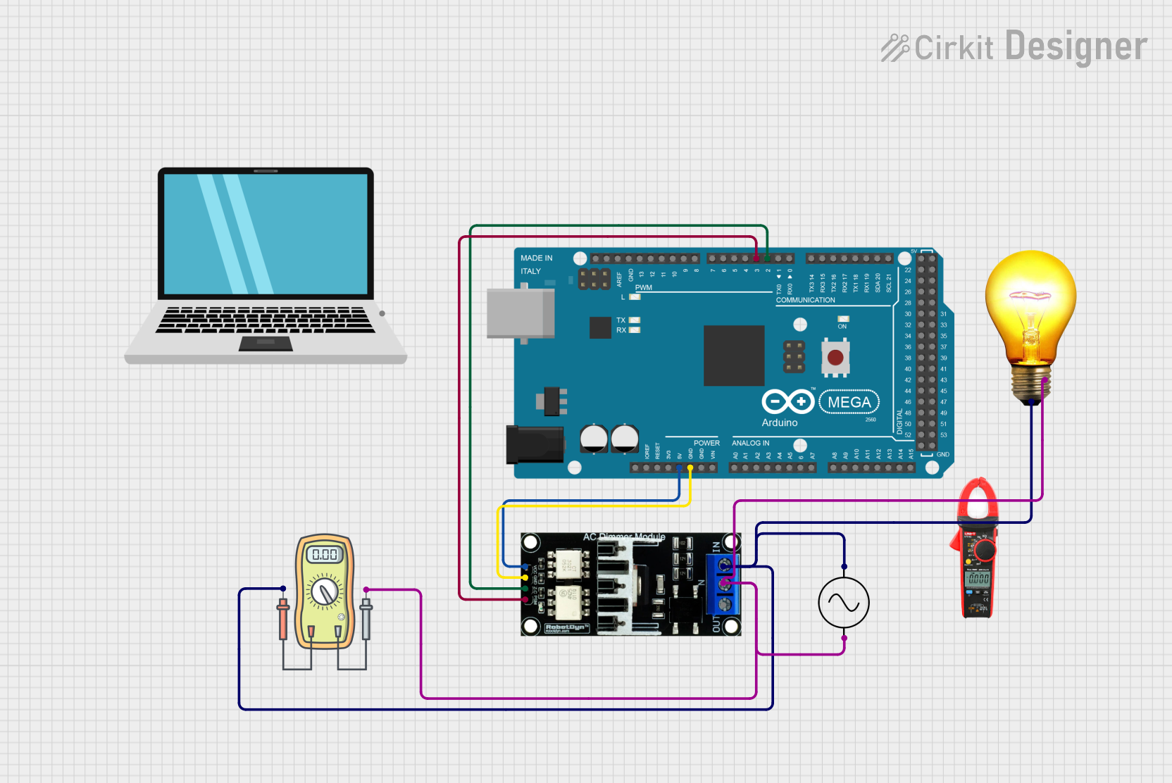
This circuit involves an Arduino Mega 2560 microcontroller controlling an AC Dimmer Lamp Module, which in turn controls an AC Bulb. The circuit also includes a voltmeter to measure the voltage across the AC Bulb and an AC power supply to provide the necessary power.
Component List
Ac Supply
- Description: Provides AC power to the circuit.
- Pins: +ve, -ve
AC Dimmer Lamp Module
- Description: Controls the brightness of an AC Bulb using PWM signals.
- Pins: VCC, GND, Z-C, PWM, N, L
Arduino Mega 2560
- Description: Microcontroller used to control the AC Dimmer Lamp Module.
- Pins: IOREF, RESET, 3V3, 5V, GND, VIN, A0, A1, A2, A3, A4, A5, A6, A7, A8, A9, A10, A11, A12, A13, A14, A15, D21/SCL, D20/SDA, D19/RX1, D18/TX1, D17 PWM/RX2, D16 PWM/TX2, D15/RX3, D14/TX3, D0 RX0, D1 TX0, D2 PWM, D3 PWM, D4 PWM, D5 PWM, D6 PWM, D7 PWM, D8 PWM, D9 PWM, D10 PWM, D11 PWM, D12 PWM, D13 PWM, AREF, SDA, SCL, D52, D50, D48, D46, D44, D42, D40, D38, D36, D34, D32, D30, D28, D26, D24, D22, D53, D51, D49, D47, D45, D43, D41, D39, D37, D35, D33, D31, D29, D27, D25, D23
Laptop
- Description: Used for programming and monitoring the Arduino Mega 2560.
- Pins: pin
Voltmeter
- Description: Measures the voltage across the AC Bulb.
- Pins: +, -
Clampmeter
- Description: Measures the current in the circuit.
- Pins: None
AC Bulb
- Description: The load controlled by the AC Dimmer Lamp Module.
- Pins: P, N
Wiring Details
Ac Supply
+ve is connected to:
- Voltmeter: +
- AC Dimmer Lamp Module: L
- AC Bulb: P
-ve is connected to:
- Voltmeter: -
- AC Dimmer Lamp Module: N
- AC Bulb: N
AC Dimmer Lamp Module
VCC is connected to:
- Arduino Mega 2560: 5V
GND is connected to:
- Arduino Mega 2560: GND
Z-C is connected to:
- Arduino Mega 2560: D2 PWM
PWM is connected to:
- Arduino Mega 2560: D3 PWM
N is connected to:
- Ac Supply: -ve
- Voltmeter: -
- AC Bulb: N
L is connected to:
- Ac Supply: +ve
- Voltmeter: +
- AC Bulb: P
Arduino Mega 2560
5V is connected to:
- AC Dimmer Lamp Module: VCC
GND is connected to:
- AC Dimmer Lamp Module: GND
D2 PWM is connected to:
- AC Dimmer Lamp Module: Z-C
D3 PWM is connected to:
- AC Dimmer Lamp Module: PWM
Voltmeter
+ is connected to:
- Ac Supply: +ve
- AC Dimmer Lamp Module: L
- AC Bulb: P
- is connected to:
- Ac Supply: -ve
- AC Dimmer Lamp Module: N
- AC Bulb: N
AC Bulb
P is connected to:
- Ac Supply: +ve
- Voltmeter: +
- AC Dimmer Lamp Module: L
N is connected to:
- Ac Supply: -ve
- Voltmeter: -
- AC Dimmer Lamp Module: N
Documented Code
Arduino Mega 2560 Code
void setup() {
  // put your setup code here, to run once:

}

void loop() {
  // put your main code here, to run repeatedly:

}
This code is a basic template for the Arduino Mega 2560. The setup function is used to initialize any settings or configurations, and the loop function contains the main code that runs repeatedly.