
Arduino UNO-Based Smart Light with PIR Sensor and Bluetooth Control
View and Edit Project In Cirkit Designer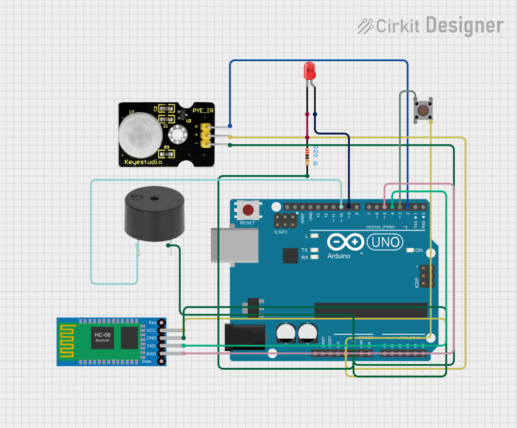
Circuit Documentation
Summary
This circuit is designed to control an LED and a buzzer using a PIR sensor, a pushbutton, and a Bluetooth module. The Arduino UNO microcontroller is the central unit that processes inputs from the PIR sensor and the pushbutton, and controls the LED and buzzer accordingly. The Bluetooth module allows for remote control of the LED.
Component List
Arduino UNO
- Description: A microcontroller board based on the ATmega328P.
- Pins: UNUSED, IOREF, Reset, 3.3V, 5V, GND, Vin, A0, A1, A2, A3, A4, A5, SCL, SDA, AREF, D13, D12, D11, D10, D9, D8, D7, D6, D5, D4, D3, D2, D1, D0
LED: Two Pin (red)
- Description: A red LED with two pins.
- Pins: cathode, anode
Buzzer
- Description: A simple buzzer with two pins.
- Pins: PIN, GND
Pushbutton
- Description: A pushbutton with four pins.
- Pins: Pin 3 (out), Pin 4 (out), Pin 1 (in), Pin 2 (in)
Bluetooth HC-06
- Description: A Bluetooth module for wireless communication.
- Pins: VCC, GND, TXD, RXD
Resistor
- Description: A resistor with a resistance of 220 Ohms.
- Pins: pin1, pin2
PIR Sensor
- Description: A Passive Infrared (PIR) sensor for motion detection.
- Pins: GND, VCC, Data
Wiring Details
Arduino UNO
5V is connected to:
- Pushbutton Pin 4 (out)
- PIR Sensor VCC
- Bluetooth HC-06 VCC
GND is connected to:
- PIR Sensor GND
- Bluetooth HC-06 GND
- Resistor pin2
- Buzzer GND
D10 is connected to Buzzer PIN
D9 is connected to LED anode
D5 is connected to Bluetooth HC-06 RXD
D4 is connected to Bluetooth HC-06 TXD
D3 is connected to Pushbutton Pin 1 (in)
D2 is connected to PIR Sensor Data
LED: Two Pin (red)
- anode is connected to Arduino UNO D9
- cathode is connected to Resistor pin1
Buzzer
- PIN is connected to Arduino UNO D10
- GND is connected to Arduino UNO GND
Pushbutton
- Pin 4 (out) is connected to Arduino UNO 5V
- Pin 1 (in) is connected to Arduino UNO D3
Bluetooth HC-06
- VCC is connected to Arduino UNO 5V
- GND is connected to Arduino UNO GND
- RXD is connected to Arduino UNO D5
- TXD is connected to Arduino UNO D4
Resistor
- pin1 is connected to LED cathode
- pin2 is connected to Arduino UNO GND
PIR Sensor
- VCC is connected to Arduino UNO 5V
- GND is connected to Arduino UNO GND
- Data is connected to Arduino UNO D2
Code Documentation
Arduino UNO Code
int pirPin = 2;
int ledPin = 9;
int buzzerPin = 10;
int buttonPin = 3;
int bluetoothPin = 4;
unsigned long timer = 0;
int delayTime = 300000;
bool lightOn = false;

void setup() {
  pinMode(pirPin, INPUT);
  pinMode(ledPin, OUTPUT);
  pinMode(buzzerPin, OUTPUT);
  pinMode(buttonPin, INPUT_PULLUP);
  Serial.begin(9600);
}

void loop() {
  int pirState = digitalRead(pirPin);
  int buttonState = digitalRead(buttonPin);

  if (buttonState == LOW) {
    lightOn = !lightOn;
    digitalWrite(ledPin, lightOn ? HIGH : LOW);
    delay(500);
  }

  if (Serial.available() > 0) {
    char command = Serial.read();
    if (command == '1') {
      digitalWrite(ledPin, HIGH);
      lightOn = true;
    }
    if (command == '0') {
      digitalWrite(ledPin, LOW);
      lightOn = false;
    }
  }

  if (pirState == HIGH && !lightOn) {
    digitalWrite(ledPin, HIGH);
    lightOn = true;
    timer = millis();
  }

  if (lightOn && millis() - timer >= delayTime) {
    for (int i = 0; i < 5; i++) {
      digitalWrite(buzzerPin, HIGH);
      delay(200);
      digitalWrite(buzzerPin, LOW);
      delay(200);
    }
    digitalWrite(ledPin, LOW);
    lightOn = false;
  }
}
This code initializes the pins for the PIR sensor, LED, buzzer, pushbutton, and Bluetooth module. It reads the state of the PIR sensor and the pushbutton, and controls the LED and buzzer accordingly. The Bluetooth module allows for remote control of the LED.