
Circuit Documentation
Summary
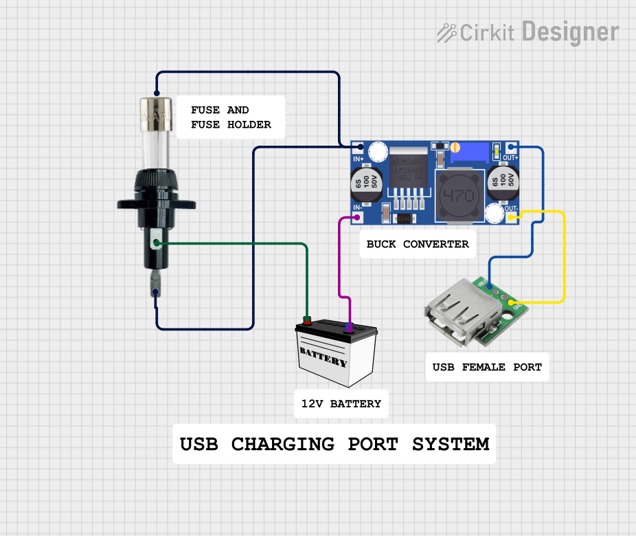
The circuit described in the provided information consists of a power supply section, a voltage regulation stage, and a USB power output interface. The power supply is provided by a small-sized 12V battery. The voltage from the battery is regulated down using a buck converter, which steps down the voltage to a level suitable for USB devices. A fuse and a fuse holder are included for overcurrent protection. The output of the buck converter is connected to a USB female port, which can be used to power or charge USB devices.
Component List
Buck Converter
- Pins: IN+, IN-, OUT+, OUT-
- Description: A buck converter is used to step down the voltage from the battery to a lower voltage suitable for USB devices.
12V Battery (Small Size)
- Pins: VCC, GND
- Description: This battery provides the input power to the circuit.
USB Female
- Pins: VCC, GND, -D, +D
- Description: A USB female port is used as the power output interface for USB devices.
Fuse
- Pins: Terminal 1, Terminal 2
- Description: The fuse provides overcurrent protection for the circuit.
3 Amps Fuse Holder
- Pins: 1, 2
- Description: This component holds the fuse and allows for easy replacement if necessary.
Comments
- Description: Comments are placeholders or annotations within the circuit design and do not have a physical representation.
Wiring Details
Buck Converter
- IN+ is connected to Terminal 2 of the Fuse and Pin 2 of the 3 Amps Fuse Holder.
- IN- is connected to the GND pin of the 12V Battery.
- OUT+ is connected to the VCC pin of the USB Female.
- OUT- is connected to the GND pin of the USB Female.
12V Battery (Small Size)
- VCC is connected to Pin 1 of the 3 Amps Fuse Holder.
- GND is connected to the IN- pin of the Buck Converter.
USB Female
- VCC is connected to the OUT+ pin of the Buck Converter.
- GND is connected to the OUT- pin of the Buck Converter.
- -D and +D pins are not connected in this circuit.
Fuse
- Terminal 1 is not connected in this circuit.
- Terminal 2 is connected to the IN+ pin of the Buck Converter.
3 Amps Fuse Holder
- Pin 1 is connected to the VCC pin of the 12V Battery.
- Pin 2 is connected to the IN+ pin of the Buck Converter.
Code Documentation
There is no embedded code provided for this circuit as there are no microcontrollers or programmable components listed in the parts list. Therefore, no code documentation is necessary for this circuit.