
Battery-Powered Ultrasonic Distance Sensor with LED Indicator using NodeMCU
View and Edit Project In Cirkit Designer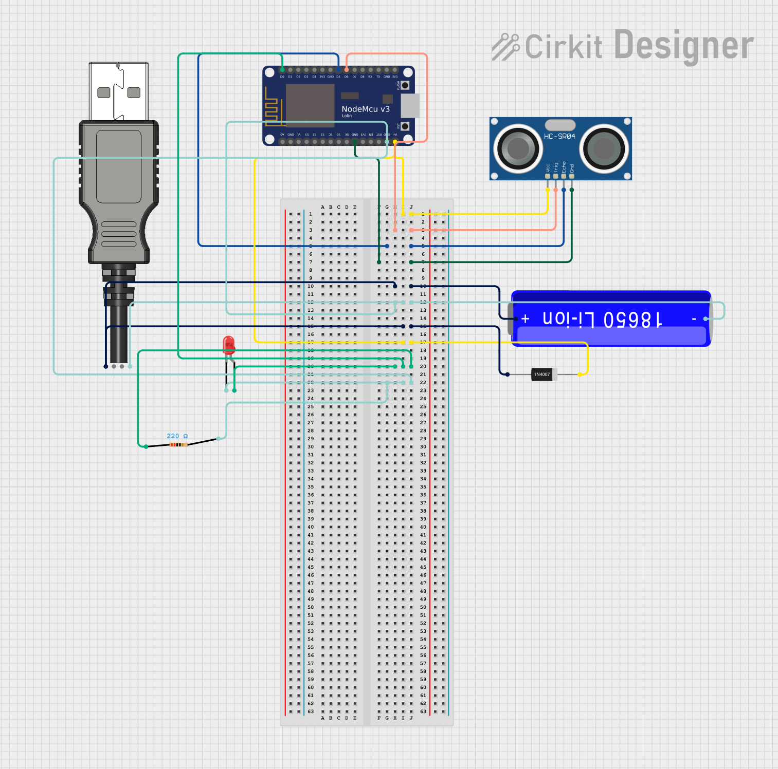
Circuit Documentation
Summary
This document provides a detailed overview of a circuit that includes an HC-SR04 Ultrasonic Sensor, a red LED, a resistor, a 1N4007 rectifier diode, a 18650 Li-ion battery, a USB plug, and a NodeMCU V3 ESP8266 microcontroller. The circuit is designed to interface the ultrasonic sensor with the NodeMCU for distance measurement, and it includes an LED indicator powered through a resistor. The power supply is managed through a 18650 Li-ion battery and a USB plug.
Component List
HC-SR04 Ultrasonic Sensor
- Pins: VCC, TRIG, ECHO, GND
- Description: Ultrasonic distance sensor used for measuring distance by sending and receiving ultrasonic waves.
LED: Two Pin (red)
- Pins: Cathode, Anode
- Description: Red LED used as an indicator.
Resistor
- Pins: Pin1, Pin2
- Description: 220 Ohms resistor used to limit current through the LED.
- Properties:
- Resistance: 220 Ohms
1N4007 Rectifier Diode
- Pins: Cathode, Anode
- Description: Diode used for rectification and protection.
18650 Li-ion Battery
- Pins: +, -
- Description: Rechargeable lithium-ion battery used as the power source.
USB Plug
- Pins: GND, D+, D-, 5V+, Out
- Description: USB plug used for power supply and data communication.
NodeMCU V3 ESP8266
- Pins: A0, GND, VU, S3, S2, S1, SC, S0, SK, 3V3, EN, RST, Vin, D0, D1, D2, D3, D4, D5, D6, D7, D8, RX, TX
- Description: Microcontroller with Wi-Fi capabilities used for controlling the circuit and interfacing with the ultrasonic sensor.
Wiring Details
HC-SR04 Ultrasonic Sensor
- VCC is connected to the Vin pin of the NodeMCU V3 ESP8266 and the Cathode pin of the 1N4007 Rectifier Diode.
- TRIG is connected to the D6 pin of the NodeMCU V3 ESP8266.
- ECHO is connected to the D5 pin of the NodeMCU V3 ESP8266.
- GND is connected to the GND pin of the NodeMCU V3 ESP8266.
LED: Two Pin (red)
- Cathode is connected to the GND pin of the NodeMCU V3 ESP8266, the - pin of the 18650 Li-ion Battery, the pin2 of the Resistor, and the GND pin of the USB Plug.
- Anode is connected to the pin1 of the Resistor and the D0 pin of the NodeMCU V3 ESP8266.
Resistor
- Pin1 is connected to the Anode of the LED and the D0 pin of the NodeMCU V3 ESP8266.
- Pin2 is connected to the Cathode of the LED, the GND pin of the NodeMCU V3 ESP8266, the - pin of the 18650 Li-ion Battery, and the GND pin of the USB Plug.
1N4007 Rectifier Diode
- Cathode is connected to the Vin pin of the NodeMCU V3 ESP8266 and the VCC pin of the HC-SR04 Ultrasonic Sensor.
- Anode is connected to the + pin of the 18650 Li-ion Battery and the 5V+ pin of the USB Plug.
18650 Li-ion Battery
- + is connected to the Anode of the 1N4007 Rectifier Diode and the 5V+ pin of the USB Plug.
- - is connected to the GND pin of the NodeMCU V3 ESP8266, the pin2 of the Resistor, the Cathode of the LED, and the GND pin of the USB Plug.
USB Plug
- 5V+ is connected to the Anode of the 1N4007 Rectifier Diode and the + pin of the 18650 Li-ion Battery.
- GND is connected to the GND pin of the NodeMCU V3 ESP8266, the pin2 of the Resistor, the Cathode of the LED, and the - pin of the 18650 Li-ion Battery.
NodeMCU V3 ESP8266
- Vin is connected to the Cathode of the 1N4007 Rectifier Diode and the VCC pin of the HC-SR04 Ultrasonic Sensor.
- D6 is connected to the TRIG pin of the HC-SR04 Ultrasonic Sensor.
- D5 is connected to the ECHO pin of the HC-SR04 Ultrasonic Sensor.
- GND is connected to the GND pin of the HC-SR04 Ultrasonic Sensor, the pin2 of the Resistor, the Cathode of the LED, the - pin of the 18650 Li-ion Battery, and the GND pin of the USB Plug.
- D0 is connected to the pin1 of the Resistor and the Anode of the LED.
Code
There is no code provided for the microcontrollers in this circuit.