Solar-Powered Wi-Fi Water Valve Controller with Battery Backup
Circuit Documentation
Summary
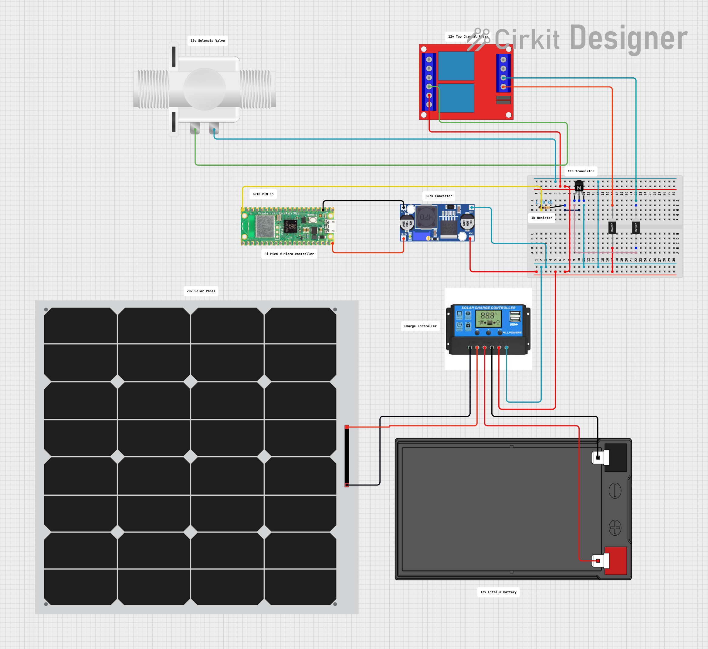
This circuit is designed to control a plastic solenoid valve using a Raspberry Pi Pico W microcontroller. The circuit includes a solar panel connected to a charge controller, which charges a 12V 7Ah battery. The battery provides power to a 2-channel 12V relay, which is used to control the solenoid valve. A buck converter steps down the voltage from the microcontroller to power the relay. The circuit also includes a resistor and an NPN transistor to interface the microcontroller with the relay, and diodes for protection against reverse current.
Component List
Microcontroller
- Raspberry Pi Pico W (PicoW)
- A microcontroller board with Wi-Fi capabilities and multiple GPIO pins.
Power Components
- Solar Panel
- Converts sunlight into electrical energy to charge the battery through the charge controller.
- Charge Controller
- Manages the charging of the battery from the solar panel and provides power to the load.
- 12V 7Ah Battery
- Stores electrical energy and provides a stable power supply to the circuit.
- Buck Converter
- Steps down the voltage from the microcontroller to a lower level suitable for the relay.
Control Components
- Plastic Solenoid Valve
- An electrically-controlled valve used for controlling the flow of a fluid.
- 2 Channel 12V Relay
- An electromechanical switch used for turning the solenoid valve on and off.
- NPN Transistor (CBE)
- Acts as a switch to control the relay with a signal from the microcontroller.
Protection Components
- 1N4007 Rectifier Diode
- Prevents reverse current that could potentially damage the circuit.
Passive Components
- Resistor
- Limits the current to the base of the NPN transistor.
Wiring Details
Raspberry Pi Pico W (PicoW)
GP15connected to one end of the Resistor.VBUSconnected toIN+on the Buck Converter.GNDconnected toOUT-on the Buck Converter.
Plastic Solenoid Valve
pin1connected toNO1on the 2 Channel 12V Relay.pin2connected toLoad Negativeon the Charge Controller.
Solar Panel
+connected toSolar Positiveon the Charge Controller.-connected toSolar Negativeon the Charge Controller.
Charge Controller
Battery Positiveconnected to12v +on the 12V 7Ah Battery.Battery Negativeconnected to12v -on the 12V 7Ah Battery.Load Positiveconnected toIN+on the Buck Converter andCOM1on the 2 Channel 12V Relay.
12V 7Ah Battery
12v +connected toBattery Positiveon the Charge Controller.12v -connected toBattery Negativeon the Charge Controller.
Resistor
- One end connected to
GP15on the PicoW. - The other end connected to
baseon the NPN Transistor (CBE).
NPN Transistor (CBE)
baseconnected topin2on the Resistor.collectorconnected toAnodeon the 1N4007 Rectifier Diode.emitterconnected toLoad Negativeon the Charge Controller,IN-on the Buck Converter, andpin2on the Plastic Solenoid Valve.
1N4007 Rectifier Diode
Anodeconnected tocollectoron the NPN Transistor (CBE) andIN+on the Buck Converter.Cathodeconnected to12v +and12v -on the 2 Channel 12V Relay.
2 Channel 12V Relay
12v +connected toCathodeon the 1N4007 Rectifier Diode.12v -connected toCathodeon the 1N4007 Rectifier Diode.COM1connected toLoad Positiveon the Charge Controller.NO1connected topin1on the Plastic Solenoid Valve.
Buck Converter
IN+connected toVBUSon the PicoW andLoad Positiveon the Charge Controller.IN-connected toemitteron the NPN Transistor (CBE).OUT+connected toVBUSon the PicoW.OUT-connected toGNDon the PicoW.
Documented Code
Raspberry Pi Pico W (PicoW) - sketch.ino
void setup() {
  // put your setup code here, to run once:

}

void loop() {
  // put your main code here, to run repeatedly:

}
Raspberry Pi Pico W (PicoW) - documentation.txt
(No additional documentation provided for the code)
This concludes the documentation for the given circuit. The circuit is designed to be powered by renewable energy from the solar panel and is capable of controlling a solenoid valve through the microcontroller and relay. The provided code template is a starting point for further development of the control logic.