
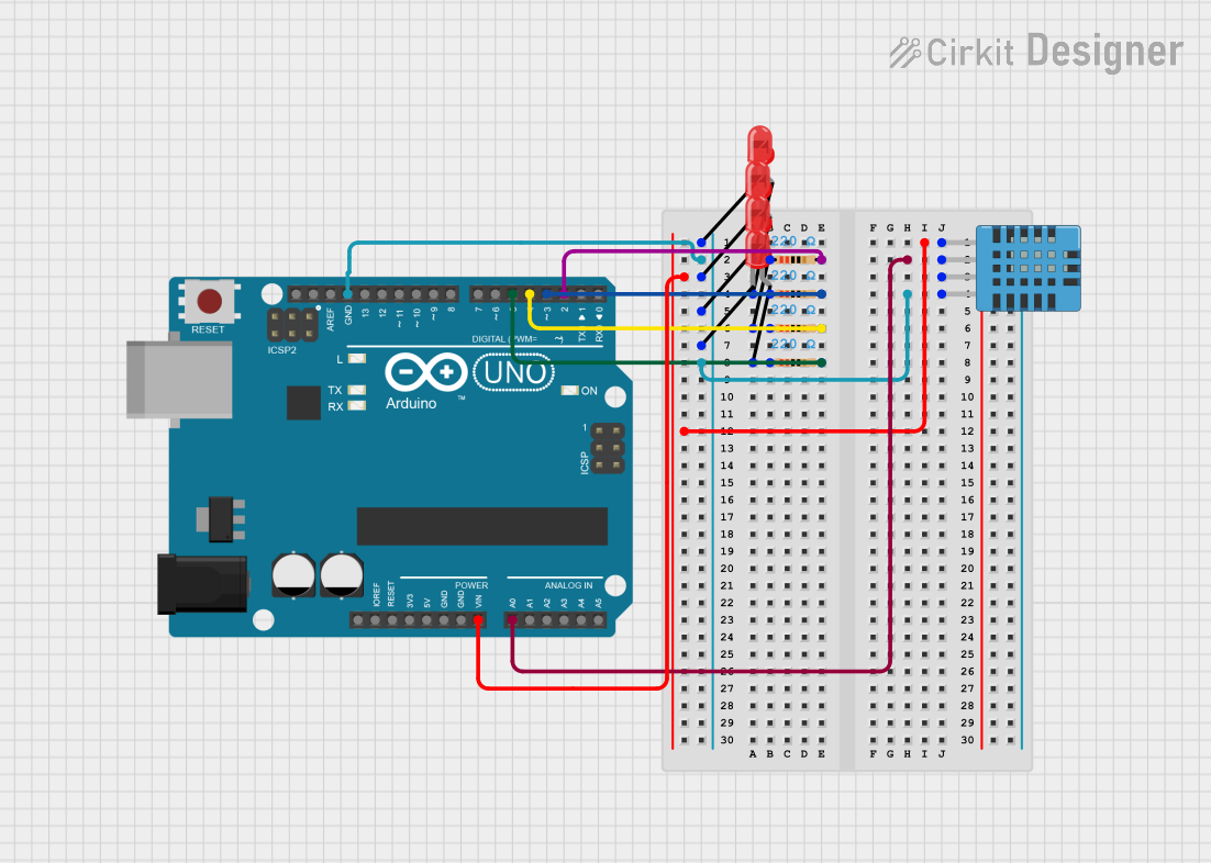
Circuit Documentation
Summary
This circuit is designed to read humidity levels using a DHT11 sensor and display the humidity level using four red LEDs. The LEDs are controlled by an Arduino UNO, which reads the humidity data from the DHT11 sensor and lights up a corresponding number of LEDs based on the humidity level.
Component List
LED: Two Pin (red)
- Description: A standard red LED with two pins: anode and cathode.
- Pins:
- Cathode
- Anode
DHT11 Humidity and Temperature Sensor
- Description: A sensor used to measure humidity and temperature.
- Pins:
- VDD
- DATA
- NULL
- GND
Arduino UNO
- Description: A microcontroller board based on the ATmega328P.
- Pins:
- UNUSED
- IOREF
- Reset
- 3.3V
- 5V
- GND
- Vin
- A0
- A1
- A2
- A3
- A4
- A5
- SCL
- SDA
- AREF
- D13
- D12
- D11
- D10
- D9
- D8
- D7
- D6
- D5
- D4
- D3
- D2
- D1
- D0
Resistor
- Description: A resistor with a resistance of 220 Ohms.
- Pins:
- Pin1
- Pin2
- Properties:
- Resistance: 220 Ohms
Wiring Details
LED: Two Pin (red)
Instance 1:
- Anode connected to Resistor pin1
- Resistor pin2 connected to Arduino UNO D2
- Cathode connected to Arduino UNO GND
Instance 2:
- Anode connected to Resistor pin1
- Resistor pin2 connected to Arduino UNO D3
- Cathode connected to Arduino UNO GND
Instance 3:
- Anode connected to Resistor pin1
- Resistor pin2 connected to Arduino UNO D4
- Cathode connected to Arduino UNO GND
Instance 4:
- Anode connected to Resistor pin1
- Resistor pin2 connected to Arduino UNO D5
- Cathode connected to Arduino UNO GND
DHT11 Humidity and Temperature Sensor
- VDD connected to Arduino UNO Vin
- DATA connected to Arduino UNO A0
- GND connected to Arduino UNO GND
Arduino UNO
- Vin connected to DHT11 VDD
- GND connected to DHT11 GND and all LED cathodes
- A0 connected to DHT11 DATA
- D2 connected to Resistor pin2 (LED Instance 1)
- D3 connected to Resistor pin2 (LED Instance 2)
- D4 connected to Resistor pin2 (LED Instance 3)
- D5 connected to Resistor pin2 (LED Instance 4)
Resistor
Instance 1:
- Pin1 connected to LED anode (Instance 1)
- Pin2 connected to Arduino UNO D2
Instance 2:
- Pin1 connected to LED anode (Instance 2)
- Pin2 connected to Arduino UNO D3
Instance 3:
- Pin1 connected to LED anode (Instance 3)
- Pin2 connected to Arduino UNO D4
Instance 4:
- Pin1 connected to LED anode (Instance 4)
- Pin2 connected to Arduino UNO D5
Code Documentation
#include <DHT.h>

#define DHTPIN A0
#define DHTTYPE DHT11

DHT dht(DHTPIN, DHTTYPE);

const int ledPins[] = {2, 3, 4, 5};

void setup() {
    for (int i = 0; i < 4; i++) {
        pinMode(ledPins[i], OUTPUT);
    }
    dht.begin();
}

void loop() {
    float humidity = dht.readHumidity();
    int numLeds = map(humidity, 0, 100, 0, 4);

    for (int i = 0; i < 4; i++) {
        if (i < numLeds) {
            digitalWrite(ledPins[i], HIGH);
        } else {
            digitalWrite(ledPins[i], LOW);
        }
    }

    delay(2000);
}
This code initializes the DHT11 sensor and sets up the LED pins as outputs. In the main loop, it reads the humidity value from the DHT11 sensor and maps it to a number between 0 and 4. It then lights up the corresponding number of LEDs based on the humidity level. The loop runs every 2 seconds.