
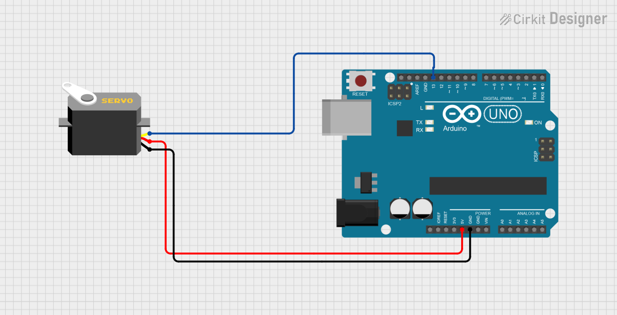
Circuit Documentation
Summary of the Circuit
The circuit in question consists of an Arduino UNO microcontroller board interfaced with a servo motor. The Arduino UNO provides control signals to the servo motor and powers it. The servo motor is expected to receive a PWM (Pulse Width Modulation) signal from one of the digital pins of the Arduino UNO to control its position. The power to the servo is supplied directly from the Arduino's 5V output pin, and the ground is shared between the two components.
Component List
Arduino UNO
- Description: A microcontroller board based on the ATmega328P. It has 14 digital input/output pins, 6 analog inputs, a 16 MHz quartz crystal, a USB connection, a power jack, an ICSP header, and a reset button.
- Pins: UNUSED, IOREF, Reset, 3.3V, 5V, GND, Vin, A0-A5, SCL, SDA, AREF, D0-D13
- Purpose: Acts as the central controller for the circuit, providing logic and control signals to the servo motor.
Servo
- Description: An actuator that has the ability to be positioned to a specific angular position by sending it a PWM signal.
- Pins: gnd, vcc, pulse
- Purpose: To perform mechanical actions as directed by the control signals from the Arduino UNO.
Wiring Details
Arduino UNO
- 5V connected to Servo (vcc)
- GND connected to Servo (gnd)
- D13 connected to Servo (pulse)
Servo
- vcc connected to Arduino UNO (5V)
- gnd connected to Arduino UNO (GND)
- pulse connected to Arduino UNO (D13)
Documented Code
Arduino UNO Code (sketch.ino)
void setup() {
  // put your setup code here, to run once:

}

void loop() {
  // put your main code here, to run repeatedly:

}
Note: The provided code is a template and does not contain any specific logic to control the servo motor. The user is expected to fill in the setup and loop functions with the necessary code to generate a PWM signal on pin D13 to control the servo.
Additional Files
- documentation.txt: This file is mentioned in the input but contains no code or text. It is likely intended for additional notes or documentation purposes.
End of Documentation