
ESP32 and MPU-6050 Controlled Servo System with Battery Power
View and Edit Project In Cirkit Designer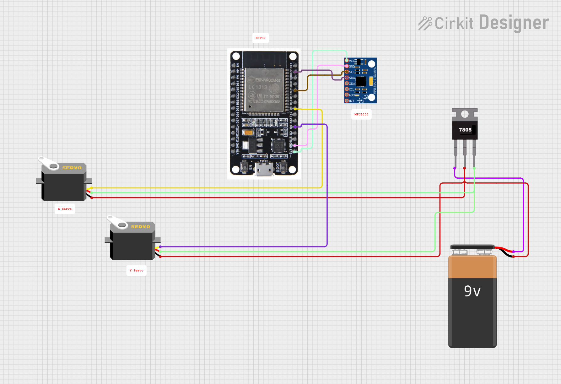
Circuit Documentation
Summary
This document provides a detailed overview of a circuit that includes an ESP32 microcontroller, an MPU-6050 accelerometer and gyroscope, two servo motors, a 7805 voltage regulator, and a 9V battery. The circuit is designed to control the servos based on data from the MPU-6050, with power regulation provided by the 7805 voltage regulator.
Component List
ESP32
- Description: A powerful microcontroller with Wi-Fi and Bluetooth capabilities.
- Pins: EN, VP, VN, D34, D35, D32, D33, D25, D26, D27, D14, D12, D13, GND, VIN, 3V3, D15, D2, D4, RX2, TX2, D5, D18, D19, D21, RX0, TX0, D22, D23, BOOT
MPU-6050
- Description: A 6-axis motion tracking device that combines a 3-axis gyroscope and a 3-axis accelerometer.
- Pins: VCC, GND, SCL, SDA, XDA, XCL, AD0, INT
Servo (x2)
- Description: A motor that can be precisely controlled to rotate to a specific angle.
- Pins: gnd, vcc, pulse
7805
- Description: A voltage regulator that outputs a stable 5V from a higher input voltage.
- Pins: Vin, Gnd, Vout
9V Battery
- Description: A standard 9V battery used to power the circuit.
- Pins: -, +
Wiring Details
ESP32
- 3V3 connected to MPU-6050 VCC
- GND connected to MPU-6050 GND
- D4 connected to Servo pulse
- D5 connected to Servo pulse
- D21 connected to MPU-6050 SCL
- D22 connected to MPU-6050 SDA
MPU-6050
- VCC connected to ESP32 3V3
- GND connected to ESP32 GND
- SCL connected to ESP32 D21
- SDA connected to ESP32 D22
Servo (1)
- gnd connected to 9V Battery - and 7805 Gnd
- vcc connected to 7805 Vout
- pulse connected to ESP32 D4
Servo (2)
- gnd connected to 9V Battery - and 7805 Gnd
- vcc connected to 7805 Vout
- pulse connected to ESP32 D5
7805
- Vin connected to 9V Battery +
- Gnd connected to 9V Battery - and Servo gnd
- Vout connected to Servo vcc
9V Battery
- - connected to 7805 Gnd and Servo gnd
- + connected to 7805 Vin
Code
No code is provided for this circuit.
This document provides a comprehensive overview of the circuit, including a summary, component list, wiring details, and code documentation. Each section is designed to help understand the purpose and connections of each component in the circuit.