Cirkit Designer
Your all-in-one circuit design IDE
Home /
Project Documentation
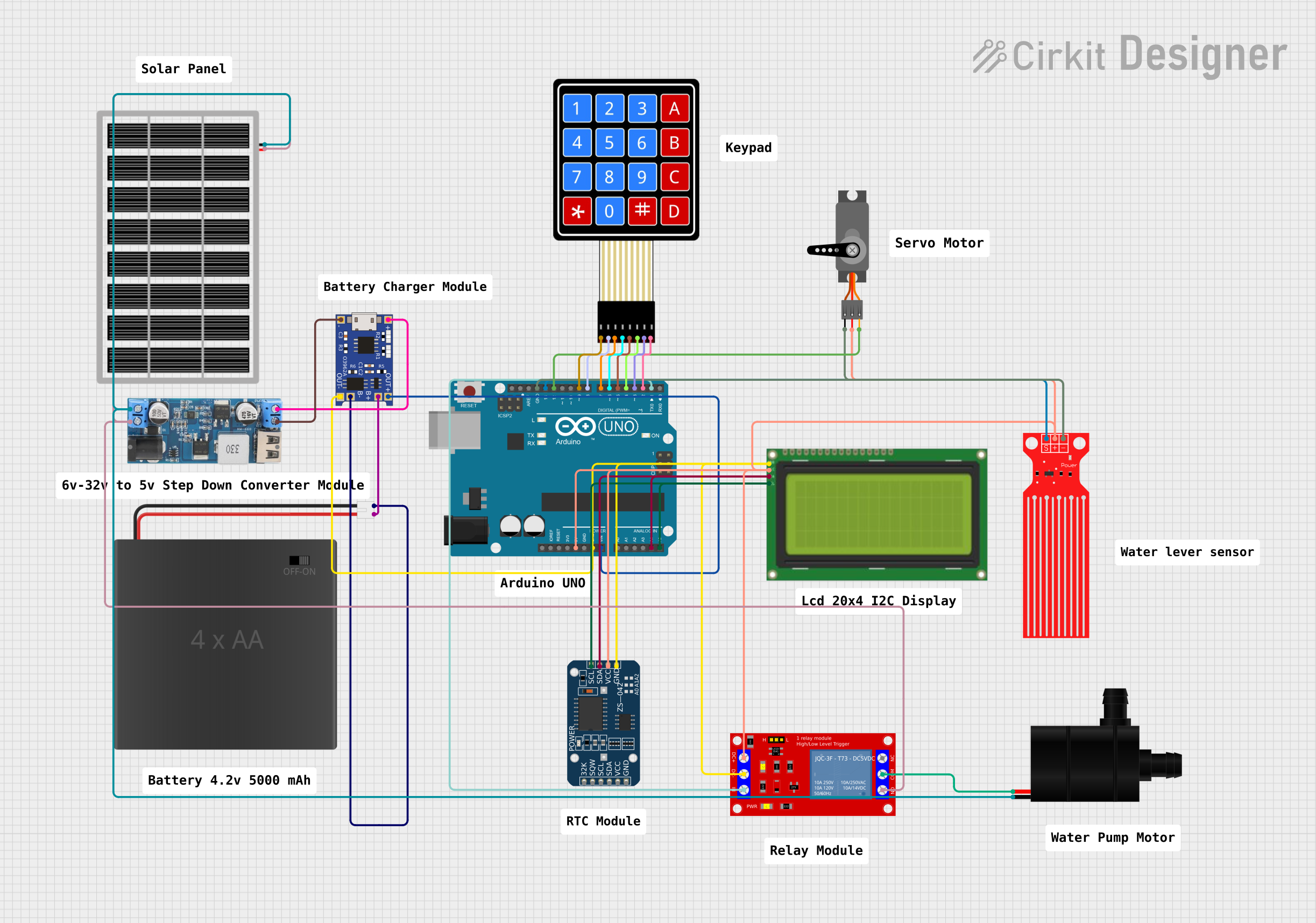
Solar-Powered Arduino UNO Water Management System with LCD Interface and Time Control
Circuit Documentation
Summary
This document provides a detailed overview of a circuit designed to interface various components with an Arduino UNO microcontroller. The circuit includes input devices, power management modules, a display, a real-time clock, a servo motor, a relay module, and a water pump. The Arduino UNO serves as the central processing unit, controlling the interactions between the components. The circuit is powered by a solar panel and a 4xAA battery pack through a TP4056 charging module and a 12v to 5v step-down power converter.
Component List
4X4 Membrane Matrix Keypad
- Description: A keypad with 16 buttons arranged in a 4x4 matrix.
- Pins: R1, R2, R3, R4, C1, C2, C3, C4
Servo
- Description: A motor capable of precise position control.
- Pins: GND, VCC, PWM
Solar Panel
- Description: A panel that converts solar energy into electrical power.
- Pins: gnd, vcc
TP4056
- Description: A lithium battery charging module with protection.
- Pins: OUT-, B-, B+, OUT+, IN-, IN+
Water Level Sensor
- Description: A sensor that detects the level of water.
- Pins: SIG, VCC, GND
Arduino UNO
- Description: A microcontroller board based on the ATmega328P.
- Pins: UNUSED, IOREF, Reset, 3.3V, 5V, GND, Vin, A0-A5, SCL, SDA, AREF, D0-D13
12v to 5v Step Down Power Converter
- Description: A module that steps down voltage from 12v to 5v.
- Pins: VIN 9v-36v, VIN+, VIN-, USB OUTPUT 5V, 5v OUTPUT, GND
4xAA_JST
- Description: A battery holder for four AA batteries with a JST connector.
- Pins: POS, NEG
Water Pump
- Description: A pump used for moving water.
- Pins: VCC, GND
1 Channel 5V Relay Module
- Description: A module that allows control of high power devices with low power signals.
- Pins: VCC+, VCC- (GND), IN, N.O., COM, N.C.
Lcd 20x4 i2c
- Description: A 20x4 character LCD display with an I2C interface.
- Pins: GND, 5v, SCA, SCL
ZS-042 RTC Module
- Description: A real-time clock module with I2C interface.
- Pins: 32K, SQW, SCL, SDA, VCC, GND
Wiring Details
4X4 Membrane Matrix Keypad
- R1 connected to Arduino UNO D9
- R2 connected to Arduino UNO D8
- R3 connected to Arduino UNO D7
- R4 connected to Arduino UNO D6
- C1 connected to Arduino UNO D5
- C2 connected to Arduino UNO D4
- C3 connected to Arduino UNO D3
- C4 connected to Arduino UNO D2
Servo
- GND connected to Arduino UNO GND
- VCC connected to Arduino UNO 5V
- PWM connected to Arduino UNO D12
Solar Panel
- gnd connected to 12v to 5v Step Down Power Converter VIN-
- vcc connected to 12v to 5v Step Down Power Converter VIN+
TP4056
- OUT- connected to Arduino UNO GND
- B- connected to 4xAA_JST NEG
- B+ connected to 4xAA_JST POS
- OUT+ connected to Arduino UNO Vin
- IN- connected to 12v to 5v Step Down Power Converter GND
- IN+ connected to 12v to 5v Step Down Power Converter 5v OUTPUT
Water Level Sensor
- SIG connected to Arduino UNO D13
- VCC connected to Arduino UNO 5V
- GND connected to Arduino UNO GND
12v to 5v Step Down Power Converter
- VIN 9v-36v not connected
- VIN+ connected to Solar Panel vcc
- VIN- connected to Water Pump GND and Solar Panel gnd
- USB OUTPUT 5V not connected
- 5v OUTPUT connected to TP4056 IN+
- GND connected to TP4056 IN-
Water Pump
- VCC connected to 1 Channel 5V Relay Module COM
- GND connected to 12v to 5v Step Down Power Converter VIN-
1 Channel 5V Relay Module
- VCC+ connected to Arduino UNO 5V
- VCC- (GND) connected to Arduino UNO GND
- IN connected to Arduino UNO D1
- N.O. connected to Solar Panel vcc
- COM connected to Water Pump VCC
- N.C. not connected
Lcd 20x4 i2c
- GND connected to Arduino UNO GND
- 5v connected to Arduino UNO 5V
- SCA connected to Arduino UNO A4
- SCL connected to Arduino UNO A5
ZS-042 RTC Module
- 32K not connected
- SQW not connected
- SCL connected to Arduino UNO A5
- SDA connected to Arduino UNO A4
- VCC connected to Arduino UNO 5V
- GND connected to Arduino UNO GND
Documented Code
Arduino UNO Code (sketch.ino)
void setup() {
  // put your setup code here, to run once:

}

void loop() {
  // put your main code here, to run repeatedly:

}
Additional Notes (documentation.txt)
No additional code documentation provided.