
Circuit Documentation
Summary
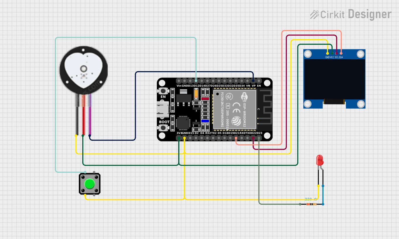
This circuit is designed to read heart pulse signals using a Heart Pulse Sensor and display the data on a 128x64 OLED Display. The circuit also includes a pushbutton and an LED, which can be controlled based on the pulse sensor readings. The ESP32 microcontroller is used to process the sensor data and control the display and LED.
Component List
ESP32 (30 pin)
- Description: A powerful microcontroller with built-in Wi-Fi and Bluetooth capabilities.
- Pins: EN, VP, VN, D34, D35, D32, D33, D25, D26, D27, D14, D12, D13, GND, Vin, D23, D22, TX0, RX0, D21, D19, D18, D5, TX2, RX2, D4, D2, D15, 3V3
Heart Pulse Sensor
- Description: A sensor used to measure heart pulse signals.
- Pins: GND, VCC, SIGNAL
Resistor
- Description: A 220 Ohm resistor used to limit current.
- Pins: pin1, pin2
- Properties: Resistance = 220 Ohms
LED: Two Pin (red)
- Description: A red LED used for visual indication.
- Pins: cathode, anode
128x64 OLED Display (I2C IIC SPI Serial)
- Description: A 128x64 pixel OLED display used to show data.
- Pins: GND, SDA, SCL, VCC
Pushbutton
- Description: A pushbutton used for user input.
- Pins: Pin 2, Pin 1, Pin 3, Pin 4
Wiring Details
ESP32 (30 pin)
- VP: Connected to Heart Pulse Sensor SIGNAL
- D12: Connected to Pushbutton Pin 1
- D23: Connected to Resistor pin1
- D22: Connected to 128x64 OLED Display SCL
- D21: Connected to 128x64 OLED Display SDA
- GND: Connected to Pushbutton Pin 2, LED cathode, 128x64 OLED Display GND, Heart Pulse Sensor GND
- 3V3: Connected to 128x64 OLED Display VCC, Heart Pulse Sensor VCC
Heart Pulse Sensor
- SIGNAL: Connected to ESP32 VP
- GND: Connected to ESP32 GND
- VCC: Connected to ESP32 3V3
Resistor
- pin1: Connected to ESP32 D23
- pin2: Connected to LED anode
LED: Two Pin (red)
- cathode: Connected to Pushbutton Pin 2, ESP32 GND
- anode: Connected to Resistor pin2
128x64 OLED Display (I2C IIC SPI Serial)
- SCL: Connected to ESP32 D22
- SDA: Connected to ESP32 D21
- GND: Connected to ESP32 GND
- VCC: Connected to ESP32 3V3
Pushbutton
- Pin 1: Connected to ESP32 D12
- Pin 2: Connected to LED cathode, ESP32 GND
- Pin 3: Not connected
- Pin 4: Not connected
Code Documentation
Sketch Code (sketch.ino)
//>>>>>>>>>>>>>>>>>>>>>>>>>>>>>>>>>>>>>>>>>>>>>>>>>>>>>>>>>>>>>>>>>>>>>>>>>>>>>>>>>>>>>>>>> 01_Test_Pulse_Sensor_and_Get_Threshold_Value
#define PulseSensor_PIN 36
#define LED_PIN         23

int Signal; //--> Accommodates the signal value (ADC value) from the pulse sensor.
// int UpperThreshold = 520;
// int LowerThreshold = 500;

//________________________________________________________________________________VOID SETUP()
void setup() {
  // put your setup code here, to run once:

  Serial.begin(115200); //--> Set's up Serial Communication at certain speed.
  Serial.println();
  delay(2000);

  // Set the ADC resolution. "analogReadResolution(10);" meaning the ADC resolution is set at 10 bits (the ADC reading value is from 0 to 1023).
  analogReadResolution(10);

  // Set LED_PIN as Output.
  pinMode(LED_PIN,OUTPUT);
}
//________________________________________________________________________________

//________________________________________________________________________________VOID LOOP()
void loop() {
  // put your main code here, to run repeatedly:

  Signal = analogRead(PulseSensor_PIN); //--> Read the PulseSensor's value. Assign this value to the "Signal" variable.

  Serial.println(Signal); //--> Send the Signal value to Serial.

  // if(Signal > UpperThreshold){ //--> If the signal is above "520"(UpperThreshold), then "turn-on" the LED.
  //   digitalWrite(LED_PIN,HIGH);
  // }

  // if(Signal < LowerThreshold){
  //   digitalWrite(LED_PIN,LOW); //--> Else, the sigal must be below "LowerThreshold", so "turn-off" the LED.
  // }

  delay(20);
}
//________________________________________________________________________________
//<<<<<<<<<<<<<<<<<<<<<<<<<<<<<<<<<<<<<<<<<<<<<<<<<<<<<<<<<<<<<<<<<<<<<<<<<<<<<<<<<<<<<<<<<
This code sets up the ESP32 to read the heart pulse signal from the Heart Pulse Sensor and print the signal value to the Serial Monitor. The LED is configured as an output, and its state can be controlled based on the pulse signal value.