Cirkit Designer
Your all-in-one circuit design IDE
Home /
Project Documentation
Arduino UNO Based Remote-Controlled Relay Switching with SIM800L and IR Receiver

Circuit Documentation
Summary
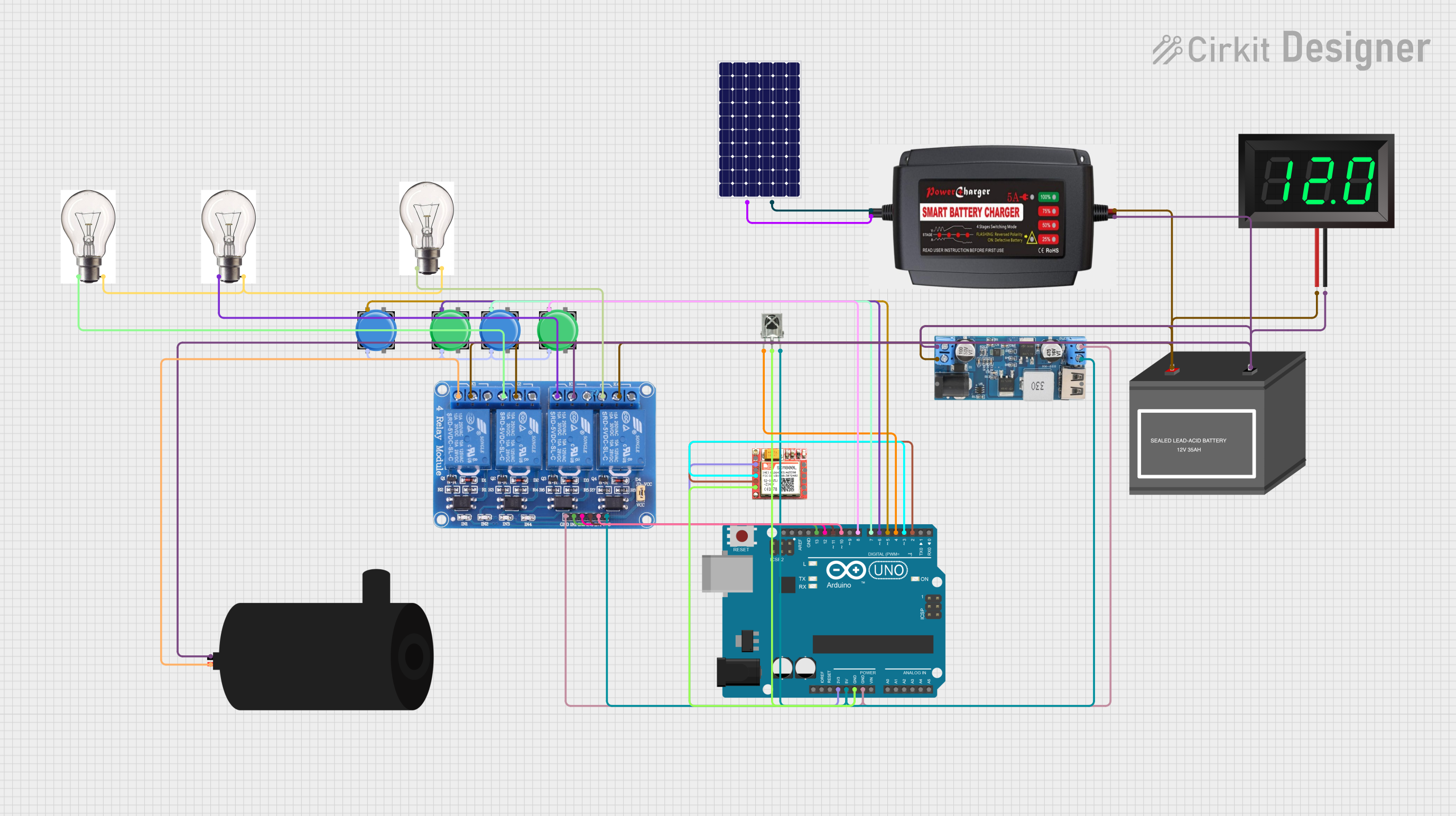
The circuit in question is designed to control a series of relays, interface with an IR receiver, and communicate via a SIM800L GSM module. It is powered by a 12V battery, which is also connected to a solar panel and a battery charger for energy sustainability. The circuit includes a step-down converter to provide the necessary 5V power to some of the components. User interaction is facilitated through pushbuttons and an IR receiver, allowing for manual control and remote control, respectively. The Arduino UNO serves as the central microcontroller, managing the inputs from the IR receiver and pushbuttons, controlling the relays, and communicating with the SIM800L module for call and SMS handling.
Component List
- Arduino UNO: A microcontroller board based on the ATmega328P, featuring digital and analog I/O pins.
- Relay 4 Channel 5V: A module with four relays that can be individually controlled to switch external circuits.
- SIM800L: A GSM/GPRS module that allows cellular communication for calls and SMS.
- VS1838B IR Receiver: An infrared receiver that captures signals from an IR remote control.
- Pushbutton: A simple switch mechanism for controlling some aspect of a machine or a process.
- Water Pump: An electric pump for moving water.
- 12V Battery (Mini): A compact battery providing 12V power supply.
- 12V Battery Charger: A device to charge the 12V battery.
- Solar Panel: A panel designed to absorb the sun's rays as a source of energy for generating electricity.
- 12V to 5V Step Down Power Converter: A device that steps down voltage from 12V to 5V.
- 7-Segment Panel Voltmeter: A digital voltmeter with a 7-segment display for voltage readout.
- Bulb: An electric light with a wire filament heated until it glows.
Wiring Details
Arduino UNO
3.3Vconnected to SIM800L VCC.5Vconnected to 12V to 5V Step Down Power Converter GND, Relay 4 Channel 5V VCC, and VS1838B IR Receiver VCC.GNDconnected to SIM800L GND, VS1838B IR Receiver GND, and 12V to 5V Step Down Power Converter 5V OUTPUT.D13connected to Relay 4 Channel 5V IN1.D12connected to Relay 4 Channel 5V IN2.D11connected to Relay 4 Channel 5V IN3.D10connected to Relay 4 Channel 5V IN4.D8connected to Pushbutton Pin 1.D7connected to Pushbutton Pin 1.D6connected to Pushbutton Pin 1.D5connected to Pushbutton Pin 1.D4connected to VS1838B IR Receiver OUT.D3connected to SIM800L RXD.D2connected to SIM800L TXD.
Relay 4 Channel 5V
GNDconnected to 12V to 5V Step Down Power Converter VIN+.COM1,COM2, andCOM4connected to 12V Battery (Mini) +.COM3connected to Water Pump Negative.NC1connected to Water Pump Positive.NC2,NC3, andNC4connected to Bulb +VE.
SIM800L
GNDconnected to Arduino UNO GND.VCCconnected to Arduino UNO 3.3V.RXDconnected to Arduino UNO D3.TXDconnected to Arduino UNO D2.
VS1838B IR Receiver
OUTconnected to Arduino UNO D4.GNDconnected to Arduino UNO GND.VCCconnected to Arduino UNO 5V.
Pushbuttons
Pin 1of each pushbutton connected to Arduino UNO D8, D7, D6, and D5 respectively.Pin 2of all pushbuttons interconnected.
Water Pump
Positiveconnected to Relay 4 Channel 5V NC1.Negativeconnected to 12V to 5V Step Down Power Converter VIN-.
12V Battery (Mini)
+connected to Relay 4 Channel 5V COM1, COM2, and COM4.-connected to 12V to 5V Step Down Power Converter VIN-.
Solar Panel
+connected to 12V Battery Charger.-connected to 12V Battery Charger.
12V to 5V Step Down Power Converter
VIN 9V-36VandVIN+connected to 12V Battery (Mini) +.VIN-connected to Water Pump Negative and 12V Battery (Mini) -.5V OUTPUTconnected to Relay 4 Channel 5V GND.
7-Segment Panel Voltmeter
V+connected to 12V Battery (Mini) +.V-connected to 12V Battery (Mini) -.
Bulbs
+VEconnected to Relay 4 Channel 5V NC2, NC3, and NC4._VEinterconnected among all bulbs.
Documented Code
/*
 * ******************************************************************
 * Created By: Tauseef Ahmad
 * Created On: September 25, 2021
 * Tutorial Link: https://youtu.be/uLJqNfX81C4
 * My Channel: https://www.youtube.com/channel/UCOXYfOHgu-C-UfGyDcu5sYw/
 *
 * ******************************************************************
 * IR Remote Version 3.3.0
 * https://github.com/Arduino-IRremote/Arduino-IRremote
 * ******************************************************************
 */

#include <SoftwareSerial.h>
#include <IRremote.h>

//sender phone number with country code
const String PHONE = "ENTER_YOUR_PERSONAL_PHONE_NUMBER";

String smsStatus,senderNumber,receivedDate,msg,buff;
boolean isReply = false;
String dtmf_cmd;
boolean is_call = false;

#define rxPin 2
#define txPin 3
SoftwareSerial sim800L(rxPin,txPin);

const byte IR_RECEIVE_PIN = 4;

#define button1_pin 5
#define button2_pin 6
#define button3_pin 7
#define button4_pin 8

#define relay1_pin 9
#define relay2_pin 10
#define relay3_pin 11
#define relay4_pin 12

boolean relay1_state = 0;
boolean relay2_state = 0;
boolean relay3_state = 0;
boolean relay4_state = 0;

void setup()
{
  pinMode(button1_pin, INPUT_PULLUP);
  pinMode(button2_pin, INPUT_PULLUP);
  pinMode(button3_pin, INPUT_PULLUP);
  pinMode(button4_pin, INPUT_PULLUP);

  pinMode(relay1_pin, OUTPUT);
  pinMode(relay2_pin, OUTPUT);
  pinMode(relay3_pin, OUTPUT);
  pinMode(relay4_pin, OUTPUT);

  Serial.begin(115200);

  Serial.println("IR Receive test");
  IrReceiver.begin(IR_RECEIVE_PIN, ENABLE_LED_FEEDBACK);

  sim800L.begin(9600);
  sim800L.print("AT+CMGF=1\r");
  delay(1000);

  sim800L.println("AT+DDET=1"); //Enable DTMF
  delay(500);

  smsStatus = "";
  senderNumber="";
  receivedDate="";
  msg="";

}

void loop()
{
  //****************************************
  while(sim800L.available()){
    buff = sim800L.readString();
    handle_sim800_response();
  }
  //****************************************
  while(Serial.available())  {
    sim800L.println(Serial.readString());
  }
  //****************************************

  listen_ir();

  listen_push_buttons();

}

void handle_sim800_response()
{
  Serial.println(buff);
    //MMMMMMMMMMMMMMMMMMMMMMMMMMMMMMMMMMMMMMMMMMMMMMMMMMMMMMMMMMMMMMMM
    if(is_call == true){
      //HHHHHHHHHHHHHHHHHHHHHHHHHHHHHHHHHHHHHHHHHHHHHHHHHHHH
      if(int index = buff.indexOf("+DTMF:") > -1 ){
        index = buff.indexOf(":");
        dtmf_cmd = buff.substring(index+1, buff.length());
        dtmf_cmd.trim();
        Serial.println("dtmf_cmd: "+dtmf_cmd);

        if(dtmf_cmd == "1")      control_relay(1);
        else if(dtmf_cmd == "2") control_relay(2);
        else if(dtmf_cmd == "3") control_relay(3);
        else if(dtmf_cmd == "4") control_relay(4);
      }
      //HHHHHHHHHHHHHHHHHHHHHHHHHHHHHHHHHHHHHHHHHHHHHHHHHHHH
      if(buff.indexOf("NO CARRIER") > -1){
        sim800L.println("ATH");
        is_call = false;
      }