
Raspberry Pi 3B-Based Multifunctional Sensor Platform with Camera
View and Edit Project In Cirkit Designer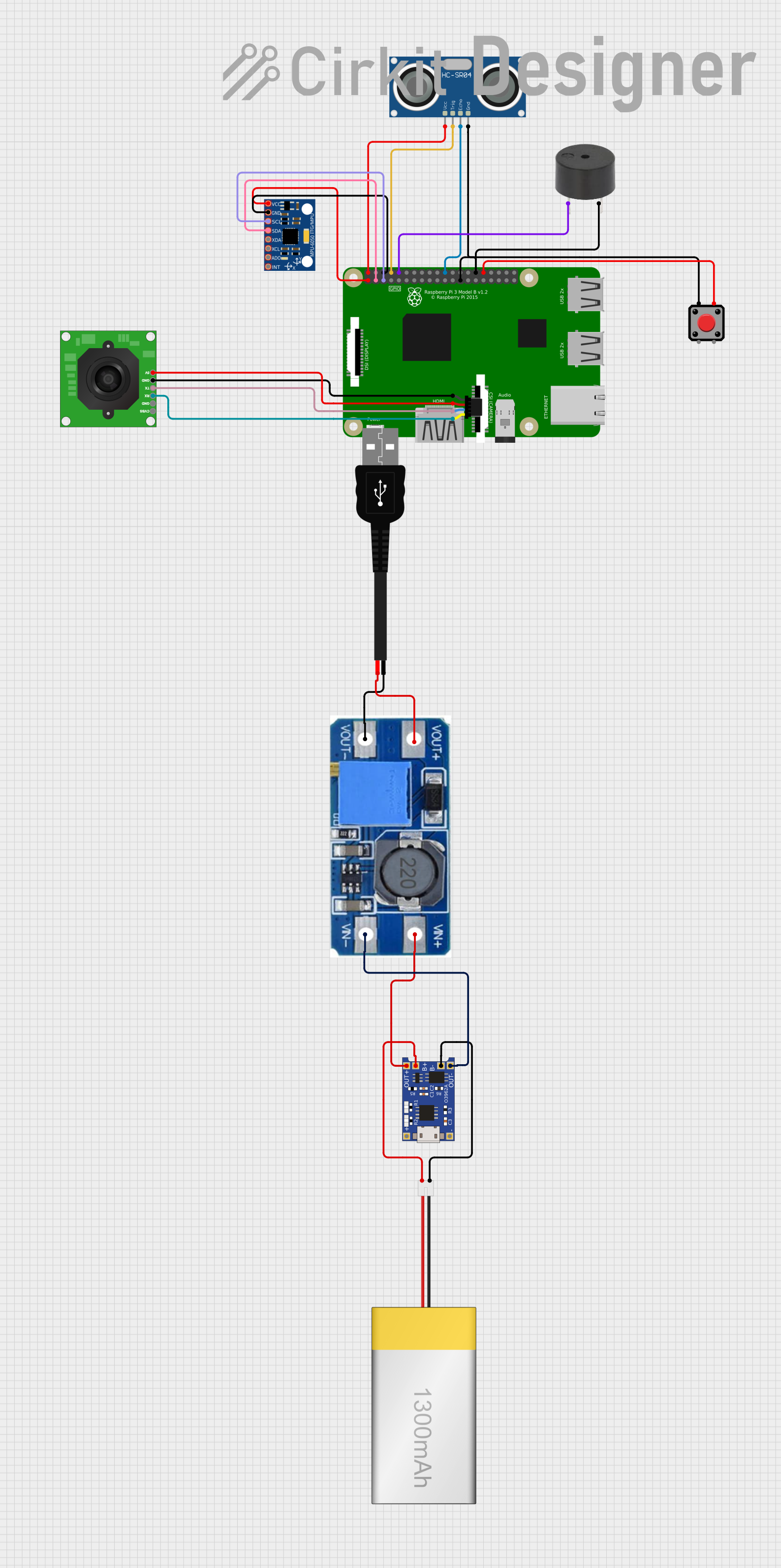
Circuit Documentation
Summary
This circuit integrates various components to interface with a Raspberry Pi 3B, including an HC-SR04 Ultrasonic Sensor, a TTL Serial JPEG Camera, an MPU-6050 accelerometer and gyroscope module, a buzzer, a pushbutton, and power management modules such as a TP4056 LiPo battery charger and a step-up boost power converter. The circuit is designed to capture images, detect motion, and provide feedback through a buzzer while managing power through a rechargeable LiPoly battery.
Component List
HC-SR04 Ultrasonic Sensor
- Description: A sensor that measures distance using ultrasonic waves.
- Pins: VCC, TRIG, ECHO, GND
Qwiic Cable - Breadboard Jumper (4-pin)
- Description: A cable used to connect I2C devices to a breadboard or other connectors.
- Pins: GND, 3.3V, SDA, SCL
Raspberry Pi 3B
- Description: A small single-board computer with GPIO pins for interfacing with various peripherals.
- Pins: Multiple GPIO pins, 3V3, 5V, GND
TTL Serial JPEG Camera
- Description: A camera module that captures JPEG images and sends them over a serial connection.
- Pins: GND, RX, TX, CVBS, 5V
TP4056
- Description: A lithium battery charger module.
- Pins: OUT-, B-, B+, OUT+, IN-, IN+
Step Up Boost Power Converter, Adjustable Voltage Regulator
- Description: A module that steps up voltage to a desired level.
- Pins: VOUT+, VOUT-, VIN+, VIN-
USB male 2 pin connection
- Description: A USB connector for power supply.
- Pins: Negative -, Positive +
LiPoly Battery (1300mAh)
- Description: A rechargeable lithium polymer battery.
- Pins: positive, negative
MPU-6050
- Description: A motion tracking device with a 3-axis gyroscope and a 3-axis accelerometer.
- Pins: VCC, GND, SCL, SDA, XDA, XCL, AD0, INT
Buzzer
- Description: An electronic buzzer for audible alerts.
- Pins: PIN, GND
Pushbutton
- Description: A simple pushbutton switch.
- Pins: Pin 2, Pin 1, Pin 3, Pin 4
Wiring Details
HC-SR04 Ultrasonic Sensor
- VCC connected to Raspberry Pi 3B 5V
- TRIG connected to Raspberry Pi 3B GPIO14
- ECHO connected to Raspberry Pi 3B GPIO25
- GND connected to Raspberry Pi 3B GND
Qwiic Cable - Breadboard Jumper (4-pin)
- GND connected to TTL Serial JPEG Camera GND
- 3.3V connected to TTL Serial JPEG Camera 5V (Note: Voltage level mismatch)
- SDA connected to TTL Serial JPEG Camera RX
- SCL connected to TTL Serial JPEG Camera TX
Raspberry Pi 3B
- Multiple GPIOs connected to various components as detailed in their respective sections.
TTL Serial JPEG Camera
- GND connected to Qwiic Cable GND
- RX connected to Qwiic Cable SDA
- TX connected to Qwiic Cable SCL
- 5V connected to Qwiic Cable 3.3V (Note: Voltage level mismatch)
TP4056
- OUT- connected to Step Up Boost Power Converter VIN-
- B- connected to LiPoly Battery negative
- B+ connected to LiPoly Battery positive
- OUT+ connected to Step Up Boost Power Converter VIN+
Step Up Boost Power Converter, Adjustable Voltage Regulator
- VOUT+ connected to USB male 2 pin connection Positive +
- VOUT- connected to USB male 2 pin connection Negative -
- VIN+ connected to TP4056 OUT+
- VIN- connected to TP4056 OUT-
USB male 2 pin connection
- Positive + connected to Step Up Boost Power Converter VOUT+
- Negative - connected to Step Up Boost Power Converter VOUT-
LiPoly Battery (1300mAh)
- positive connected to TP4056 B+
- negative connected to TP4056 B-
MPU-6050
- VCC connected to Raspberry Pi 3B 3v3
- GND connected to Raspberry Pi 3B GND
- SCL connected to Raspberry Pi 3B GPIO3
- SDA connected to Raspberry Pi 3B GPIO2
Buzzer
- PIN connected to Raspberry Pi 3B GPIO15
- GND connected to Raspberry Pi 3B GND
Pushbutton
- Pin 1 connected to Raspberry Pi 3B GND
- Pin 4 connected to Raspberry Pi 3B GPIO12
Documented Code
No code has been provided for the microcontrollers in the circuit. When code becomes available, it should be documented in this section with appropriate comments and explanations for each function and routine.