
Arduino-Based Smart Water Management System with TDS and Ultrasonic Sensors
View and Edit Project In Cirkit Designer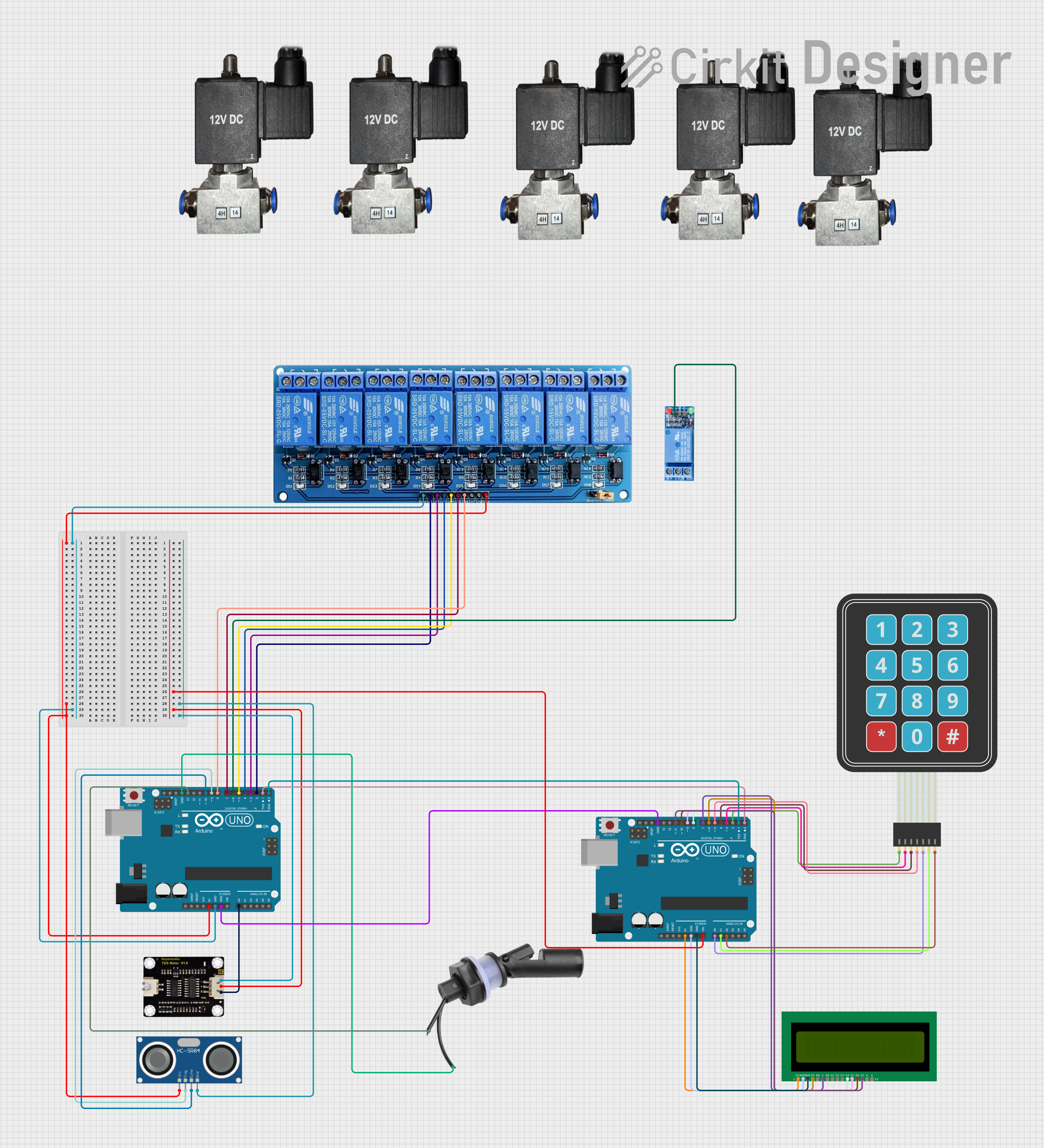
Circuit Documentation
Summary
This circuit involves two Arduino UNO microcontrollers, an HC-SR04 Ultrasonic Sensor, a TDS Sensor, a Water Level Float Switch Sensor, a 16x2 LCD, a Membrane Matrix Keypad, a 1 Channel Relay, and a 5V 8 Channel Relay. The circuit is designed to measure water levels and TDS (Total Dissolved Solids) in a tank, control various relays for water flow, and display information on an LCD. The user can interact with the system using a keypad.
Component List
Arduino UNO
- Description: Microcontroller board based on the ATmega328P.
- Pins: UNUSED, IOREF, Reset, 3.3V, 5V, GND, Vin, A0, A1, A2, A3, A4, A5, SCL, SDA, AREF, D13, D12, D11, D10, D9, D8, D7, D6, D5, D4, D3, D2, D1, D0
HC-SR04 Ultrasonic Sensor
- Description: Ultrasonic distance sensor.
- Pins: VCC, TRIG, ECHO, GND
12V Pneumatic Solenoid Valve
- Description: Solenoid valve for controlling water flow.
- Pins: VCC, GND
16x2 LCD
- Description: 16x2 character LCD display.
- Pins: VSS, VDD, V0, RS, RW, E, D1, D0, D2, D3, D4, D6, D5, D7, A, K
TDS Sensor
- Description: Sensor for measuring Total Dissolved Solids in water.
- Pins: P1, P2, +, -, A
Water Level Float Switch Sensor
- Description: Sensor for detecting water level.
- Pins: Wire2, Wire1
1 Channel Relay 5V
- Description: Single channel relay module.
- Pins: VCC, GND, IN, NC, COM, NO
5V 8 Channel Relay
- Description: 8 channel relay module.
- Pins: GND, IN1, IN2, IN3, IN4, IN5, IN6, IN7, IN8, VCC, NC, C, NO
Membrane Matrix Keypad
- Description: 4x3 membrane keypad.
- Pins: Row 1, Row 2, Row 3, Row 4, Column 1, Column 2, Column 3
Wiring Details
Arduino UNO (1)
- 5V: Connected to VCC of HC-SR04 Ultrasonic Sensor and VCC of 5V 8 Channel Relay.
- GND: Connected to GND of 5V 8 Channel Relay, GND of HC-SR04 Ultrasonic Sensor, GND of Water Level Float Switch Sensor, and GND of the second Arduino UNO.
- Vin: Connected to + of TDS Sensor.
- A0: Connected to A of TDS Sensor.
- D13: Connected to Wire1 of Water Level Float Switch Sensor.
- D10: Connected to ECHO of HC-SR04 Ultrasonic Sensor.
- D9: Connected to TRIG of HC-SR04 Ultrasonic Sensor.
- D8: Connected to IN6 of 5V 8 Channel Relay.
- D7: Connected to IN5 of 5V 8 Channel Relay.
- D6: Connected to IN of 1 Channel Relay 5V.
- D5: Connected to IN4 of 5V 8 Channel Relay.
- D4: Connected to IN3 of 5V 8 Channel Relay.
- D3: Connected to IN2 of 5V 8 Channel Relay.
- D2: Connected to IN1 of 5V 8 Channel Relay.
- D1: Connected to D0 of the second Arduino UNO.
- D0: Connected to D1 of the second Arduino UNO.
Arduino UNO (2)
- Vin: Connected to + of TDS Sensor.
- 5V: Connected to VSS of 16x2 LCD.
- GND: Connected to VDD and V0 of 16x2 LCD.
- A0: Connected to Column 1 of Membrane Matrix Keypad.
- A1: Connected to Column 2 of Membrane Matrix Keypad.
- A2: Connected to Column 3 of Membrane Matrix Keypad.
- D11: Connected to D7 of 16x2 LCD.
- D10: Connected to D6 of 16x2 LCD.
- D9: Connected to D5 of 16x2 LCD.
- D8: Connected to D4 of 16x2 LCD.
- D7: Connected to E of 16x2 LCD.
- D6: Connected to RS of 16x2 LCD.
- D5: Connected to Row 4 of Membrane Matrix Keypad.
- D4: Connected to Row 3 of Membrane Matrix Keypad.
- D3: Connected to Row 2 of Membrane Matrix Keypad.
- D2: Connected to Row 1 of Membrane Matrix Keypad.
HC-SR04 Ultrasonic Sensor
- VCC: Connected to 5V of the first Arduino UNO.
- GND: Connected to GND of the first Arduino UNO.
- TRIG: Connected to D9 of the first Arduino UNO.
- ECHO: Connected to D10 of the first Arduino UNO.
12V Pneumatic Solenoid Valve
- VCC: Not connected in the provided net list.
- GND: Not connected in the provided net list.
16x2 LCD
- VSS: Connected to 5V of the second Arduino UNO.
- VDD: Connected to GND of the second Arduino UNO.
- V0: Connected to GND of the second Arduino UNO.
- RS: Connected to D6 of the second Arduino UNO.
- E: Connected to D7 of the second Arduino UNO.
- D4: Connected to D8 of the second Arduino UNO.
- D5: Connected to D9 of the second Arduino UNO.
- D6: Connected to D10 of the second Arduino UNO.
- D7: Connected to D11 of the second Arduino UNO.
TDS Sensor
- +: Connected to Vin of the first and second Arduino UNO.
- -: Connected to GND of HC-SR04 Ultrasonic Sensor.
- A: Connected to A0 of the first Arduino UNO.
Water Level Float Switch Sensor
- Wire2: Connected to GND of the first Arduino UNO.
- Wire1: Connected to D13 of the first Arduino UNO.
1 Channel Relay 5V
- IN: Connected to D6 of the first Arduino UNO.
5V 8 Channel Relay
- VCC: Connected to 5V of the first Arduino UNO.
- GND: Connected to GND of the first Arduino UNO.
- IN1: Connected to D2 of the first Arduino UNO.
- IN2: Connected to D3 of the first Arduino UNO.
- IN3: Connected to D4 of the first Arduino UNO.
- IN4: Connected to D5 of the first Arduino UNO.
- IN5: Connected to D7 of the first Arduino UNO.
- IN6: Connected to D8 of the first Arduino UNO.
Membrane Matrix Keypad
- Row 1: Connected to D2 of the second Arduino UNO.
- Row 2: Connected to D3 of the second Arduino UNO.
- Row 3: Connected to D4 of the second Arduino UNO.
- Row 4: Connected to D5 of the second Arduino UNO.
- Column 1: Connected to A0 of the second Arduino UNO.
- Column 2: Connected to A1 of the second Arduino UNO.
- Column 3: Connected to A2 of the second Arduino UNO.
Code Documentation
Arduino UNO (1)
#define RelayNF 2
#define RelayRO 3
#define RelayPump 4
#define RelayMixing 5
#define RelayUV 6
#define RelayOut 7
#define RelayIn 8
#define trigPin 9
#define echoPin 10
#define floatControllerPin 13

#define TDS_SENSOR_PIN A0
#define VREF 5.0            // ADC reference voltage
#define SCOUNT 30           // Number of sample points for averaging

int analogBuffer[SCOUNT];     // Store analog values from ADC
int analogBufferTemp[SCOUNT]; // Temporary array for median filtering
int analogBufferIndex = 0;
float averageVoltage = 0;
float temperature =