Cirkit Designer
Your all-in-one circuit design IDE
Home /
Project Documentation
Arduino-Controlled Dual DC Motor Driver Circuit with L298N and SPST Switch
Circuit Documentation
Summary
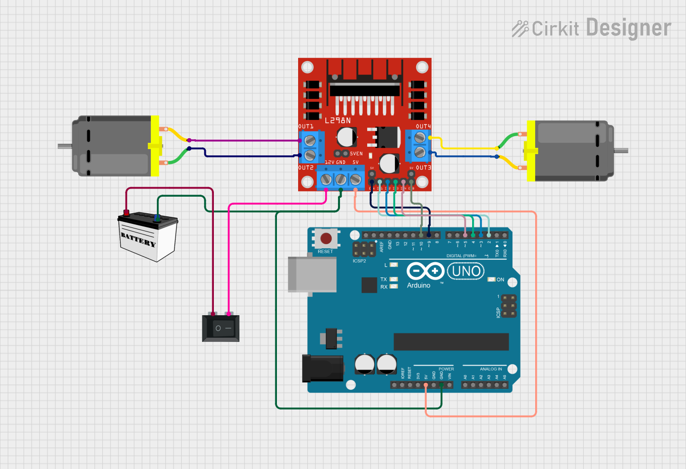
This circuit is designed to control two DC motors using an L298N DC motor driver, which is interfaced with an Arduino UNO microcontroller. The motors can be powered on and off using a 12V battery connected through a rocker switch (SPST). The Arduino UNO provides control signals to the L298N driver to regulate the direction and speed of the motors using PWM (Pulse Width Modulation). The circuit is powered by the 12V battery, with the Arduino receiving 5V from its onboard voltage regulator.
Component List
L298N DC Motor Driver
- Description: A motor driver module capable of driving two DC motors.
- Purpose: To control the direction and speed of two DC motors.
- Pins: OUT1, OUT2, 12V, GND, 5V, OUT3, OUT4, 5V-ENA-JMP-I, 5V-ENA-JMP-O, +5V-J1, +5V-J2, ENA, IN1, IN2, IN3, IN4, ENB.
DC Motor (x2)
- Description: A standard DC motor for converting electrical energy into mechanical rotation.
- Purpose: To perform mechanical work when powered by the motor driver.
- Pins: pin 1, pin 2.
Arduino UNO
- Description: A microcontroller board based on the ATmega328P.
- Purpose: To provide control signals to the motor driver for motor operation.
- Pins: UNUSED, IOREF, Reset, 3.3V, 5V, GND, Vin, A0-A5, SCL, SDA, AREF, D0-D13.
12V Battery (Small Size)
- Description: A power source providing 12V DC.
- Purpose: To supply power to the motor driver and indirectly to the motors.
- Pins: VCC, GND.
Rocker Switch (SPST)
- Description: A single-pole single-throw switch.
- Purpose: To control the power supply from the battery to the motor driver.
- Pins: 1, 2.
Wiring Details
L298N DC Motor Driver
- 5V: Connected to Arduino UNO 5V.
- GND: Common ground with Arduino UNO and 12V Battery.
- 12V: Connected to Rocker Switch pin 2.
- ENA, IN1, IN2: Controlled by Arduino UNO pins D9, D2, D3 respectively.
- ENB, IN3, IN4: Controlled by Arduino UNO pins D10, D4, D5 respectively.
- OUT1, OUT2: Connected to one DC Motor.
- OUT3, OUT4: Connected to the other DC Motor.
DC Motor #1
- pin 1: Connected to L298N DC motor driver OUT2.
- pin 2: Connected to L298N DC motor driver OUT1.
DC Motor #2
- pin 1: Connected to L298N DC motor driver OUT4.
- pin 2: Connected to L298N DC motor driver OUT3.
Arduino UNO
- 5V: Supplies power to L298N DC motor driver.
- GND: Common ground with L298N DC motor driver and 12V Battery.
- D2, D3, D4, D5, D9, D10: Control signals to L298N DC motor driver.
12V Battery
- VCC: Connected to Rocker Switch pin 1.
- GND: Common ground with Arduino UNO and L298N DC motor driver.
Rocker Switch (SPST)
- Pin 1: Connected to 12V Battery VCC.
- Pin 2: Connected to L298N DC motor driver 12V.
Documented Code
Arduino UNO Code
/*
 * This Arduino sketch controls two DC motors connected to an L298N motor driver.
 * The motors are set to spin in opposite directions, and their speed (RPM) can
 * be controlled using PWM signals. The motor driver is connected to the Arduino
 * as follows:
 * - ENA (Motor A enable) -> D9
 * - IN1 (Motor A input 1) -> D2
 * - IN2 (Motor A input 2) -> D3
 * - ENB (Motor B enable) -> D10
 * - IN3 (Motor B input 1) -> D4
 * - IN4 (Motor B input 2) -> D5
 */

// Define motor control pins
const int ENA = 9;
const int IN1 = 2;
const int IN2 = 3;
const int ENB = 10;
const int IN3 = 4;
const int IN4 = 5;

void setup() {
  // Set all the motor control pins to output mode
  pinMode(ENA, OUTPUT);
  pinMode(IN1, OUTPUT);
  pinMode(IN2, OUTPUT);
  pinMode(ENB, OUTPUT);
  pinMode(IN3, OUTPUT);
  pinMode(IN4, OUTPUT);

  // Initialize motors to spin in opposite directions
  digitalWrite(IN1, HIGH);
  digitalWrite(IN2, LOW);
  digitalWrite(IN3, LOW);
  digitalWrite(IN4, HIGH);
}

void loop() {
  // Set motor speed using PWM (0-255)
  int speed = 128; // Example speed value, can be adjusted
  analogWrite(ENA, speed);
  analogWrite(ENB, speed);

  // Add any additional logic here if needed
}
DC Motor Microcontroller Code
The DC motors in this circuit do not have associated microcontroller code as they are directly controlled by the L298N motor driver, which in turn is controlled by the Arduino UNO.