Cirkit Designer
Your all-in-one circuit design IDE
Home /
Project Documentation
Arduino-Powered EMG Sensor-Controlled Dual Servo System
Circuit Documentation
Summary
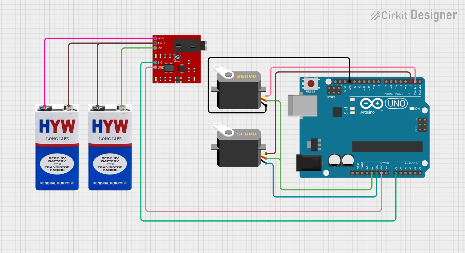
This circuit involves an Arduino UNO microcontroller interfacing with an EMG sensor and two servos. The EMG sensor is powered by two 9V batteries and sends its signal to the Arduino, which then controls the servos based on the sensor input.
Component List
EMG SENSOR
- Description: Measures muscle activity by detecting the electrical potential generated by muscle cells.
- Pins: +Vs, GND, -Vs, SIG
9V battery
- Description: Provides power to the circuit.
- Pins: +, -
Arduino UNO
- Description: A microcontroller board based on the ATmega328P, used for prototyping and development.
- Pins: UNUSED, IOREF, Reset, 3.3V, 5V, GND, Vin, A0, A1, A2, A3, A4, A5, SCL, SDA, AREF, D13, D12, D11, D10, D9, D8, D7, D6, D5, D4, D3, D2, D1, D0
Servo (2 units)
- Description: A rotary actuator that allows for precise control of angular position.
- Pins: gnd, vcc, pulse
Wiring Details
EMG SENSOR
- +Vs connected to + of the first 9V battery.
- GND connected to - of the first 9V battery and GND of the Arduino UNO.
- -Vs connected to - of the second 9V battery.
- SIG connected to A0 of the Arduino UNO.
9V battery (first)
- + connected to +Vs of the EMG SENSOR.
- - connected to + of the second 9V battery and GND of the EMG SENSOR.
9V battery (second)
- + connected to - of the first 9V battery.
- - connected to -Vs of the EMG SENSOR.
Arduino UNO
- GND connected to GND of the EMG SENSOR, gnd of the first Servo, and gnd of the second Servo.
- 5V connected to vcc of the first Servo and vcc of the second Servo.
- A0 connected to SIG of the EMG SENSOR.
- D2 connected to pulse of the first Servo.
- D1 connected to pulse of the second Servo.
Servo (first)
- gnd connected to GND of the Arduino UNO.
- vcc connected to 5V of the Arduino UNO.
- pulse connected to D2 of the Arduino UNO.
Servo (second)
- gnd connected to GND of the Arduino UNO.
- vcc connected to 5V of the Arduino UNO.
- pulse connected to D1 of the Arduino UNO.
Code Documentation
Arduino UNO Code
void setup() {
  // put your setup code here, to run once:

}

void loop() {
  // put your main code here, to run repeatedly:

}
This code is a basic template for the Arduino UNO. The setup() function is where you initialize your components and settings, and the loop() function is where the main logic of your program runs repeatedly.
Additional Documentation
This section is reserved for any additional documentation or notes that may be required for understanding the circuit and its operation.