
Arduino Mega and ESP32 Based Environmental Monitoring and Control System
View and Edit Project In Cirkit Designer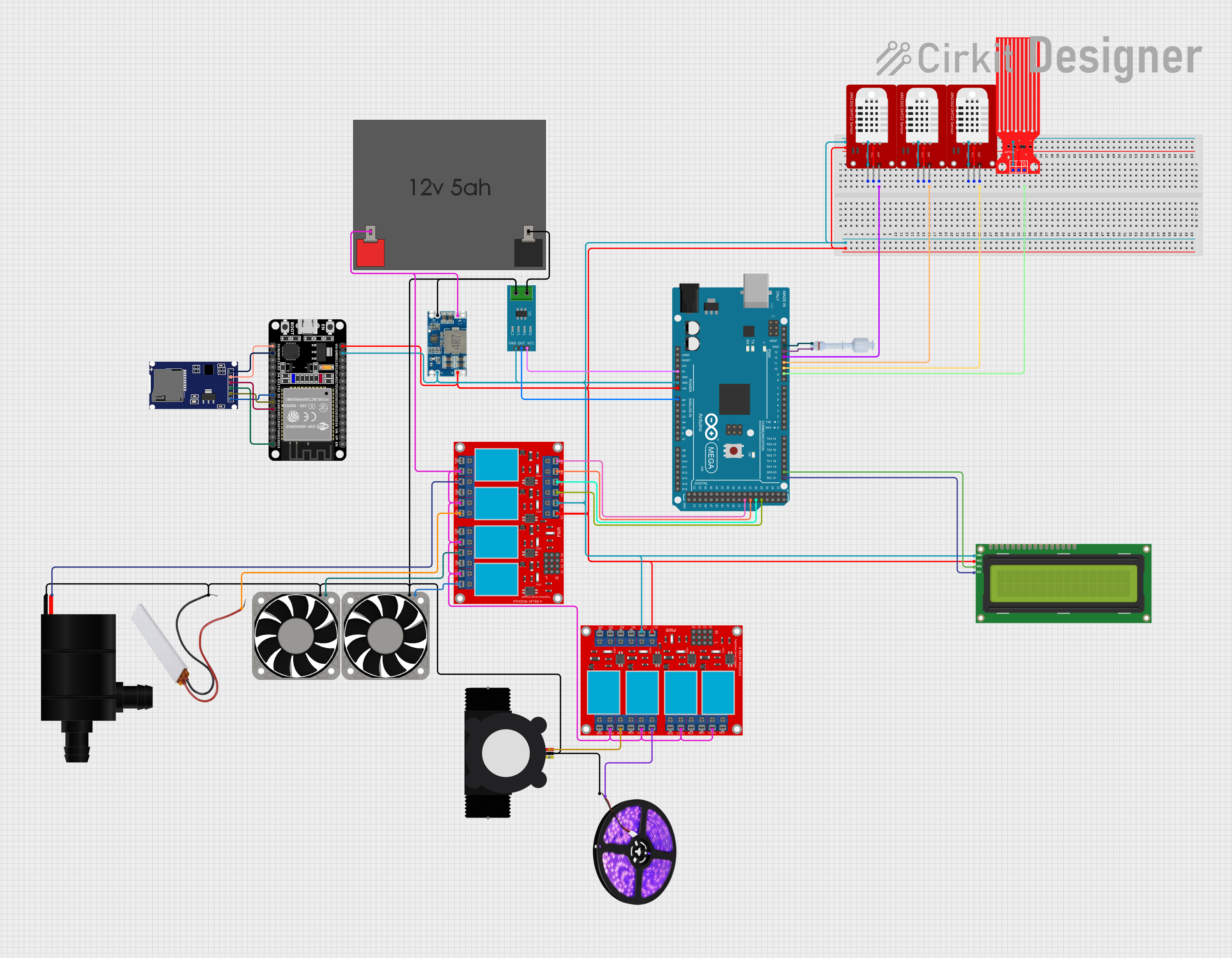
Circuit Documentation
Summary
This document provides a detailed overview of a circuit designed to interface various sensors, actuators, and modules with an Arduino Mega 2560 and an ESP32 microcontroller. The circuit includes components for environmental sensing (DHT22 sensors), water flow and level detection (YF-S201 Water Flow Meter and Water Level Sensor), a user interface (I2C LCD 16x2 Screen), power regulation (Mini 560 Step Down Converter), and control elements (4 channel relay modules). The system is powered by a 12V 5Ah battery and includes safety features such as a PTC (Positive Temperature Coefficient) thermistor.
Component List
- Arduino Mega 2560: A microcontroller board based on the ATmega2560, with numerous digital and analog I/O pins.
- ESP32 (30 pin): A microcontroller with Wi-Fi and Bluetooth capabilities, featuring a variety of GPIOs.
- Mini 560 Step Down 20-7V to 5V: A voltage regulator that steps down input voltages between 20V to 7V to a stable 5V output.
- SDmodule: An SD card module for data logging, interfacing with the ESP32 via SPI.
- 4 channel relay module: Modules used to control high power devices such as fans, pumps, and lights.
- 12v5ah Battery: A 12V battery providing power to the circuit.
- I2C LCD 16x2 Screen: A 16x2 character LCD display using the I2C communication protocol.
- DHT22: Temperature and humidity sensors.
- 40 Fan 12v: 12V cooling fans.
- PTC: A thermistor used as a resettable fuse for overcurrent protection.
- Water Pump: A pump controlled by one of the relay modules.
- YF-S201 Water Flow Meter: A sensor for measuring water flow.
- Float Switch: A switch that detects the presence of a liquid at a certain level.
- Water Level Sensor: A sensor that measures the level of water in a container.
- LED Light Strips (Violet): Violet LED strips for lighting or indication purposes.
- Current Sensor 5A: A sensor for measuring electrical current up to 5A.
Wiring Details
Arduino Mega 2560
- GND: Connected to the ground of various components for a common ground reference.
- VIN: Connected to the output of the Mini 560 Step Down Converter to power the board.
- Digital Pins (D10, D11, D12): Connected to the data pins of DHT22 sensors for temperature and humidity readings.
- Digital Pin (D13): Connected to the Float Switch for water level detection.
- Digital Pins (D29, D31, D33, D35): Connected to the input pins of the 4 channel relay module for controlling various devices.
- Analog Pin (A0): Connected to the output of the Current Sensor 5A for current measurement.
- I2C Pins (D20/SDA, D21/SCL): Connected to the I2C LCD 16x2 Screen for display purposes.
ESP32 (30 pin)
- 3V3: Powers the SDmodule.
- GND: Common ground with the SDmodule.
- Digital Pins (D5, D18, D19, D23): Connected to the SPI pins of the SDmodule for data logging.
Mini 560 Step Down 20-7V to 5V
- IN+: Connected to the 12V+ of the battery.
- IN-: Connected to the 12V- of the battery and the ground of various components.
- OUT+: Provides 5V to power the ESP32 and other 5V components.
- OUT-: Common ground for the 5V power rail.
4 channel relay module
- VCC+: Connected to the 5V output from the Mini 560 Step Down Converter.
- VCC- (GND): Common ground reference.
- IN 1-4: Control inputs from the Arduino Mega 2560.
- COM 1-4: Connected to the 12V+ from the battery.
- N.C. 1-4: Normally closed contacts connected to various devices like the Water Pump, PTC, and fans.
DHT22 Sensors
- VCC: Powered by the 5V output from the Mini 560 Step Down Converter.
- GND: Common ground reference.
- DAT: Data pins connected to the Arduino Mega 2560.
I2C LCD 16x2 Screen
- VCC (5V): Powered by the 5V output from the Mini 560 Step Down Converter.
- GND: Common ground reference.
- SDA: Connected to the SDA pin on the Arduino Mega 2560.
- SCL: Connected to the SCL pin on the Arduino Mega 2560.
SDmodule
- VCC: Powered by the 3.3V output from the ESP32.
- GND: Common ground with the ESP32.
- CS, SCK, MOSI, MISO: Connected to the corresponding SPI pins on the ESP32.
Power Connections
- 12v5ah Battery: Provides the main power source for the circuit.
- Current Sensor 5A: Placed in series with the battery's negative terminal to measure current draw.
Actuators and Sensors
- Water Pump: Controlled by a relay, connected to the PTC for protection.
- YF-S201 Water Flow Meter: Powered by a relay and provides flow rate data.
- LED Light Strips (Violet): Powered by a relay for lighting control.
- 40 Fan 12v: Controlled by relays to provide cooling as needed.
Documented Code
Arduino Mega 2560
void setup() {
  // put your setup code here, to run once:

}

void loop() {
  // put your main code here, to run repeatedly:

}
Note: The provided code for the Arduino Mega 2560 is a template and does not contain any functional code. It needs to be populated with the setup and loop functions to control the connected components based on the circuit's requirements.