Cirkit Designer
Your all-in-one circuit design IDE
Home /
Project Documentation
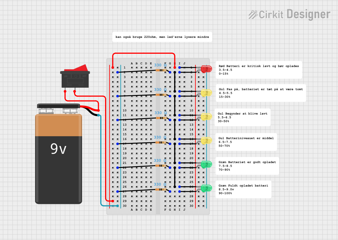
Battery-Powered LED Indicator Circuit with Rocker Switch
Circuit Documentation
Summary
This circuit consists of a 9V battery, a rocker switch, multiple LEDs of different colors (red, green, and yellow), and several resistors. The circuit is designed to light up the LEDs when the rocker switch is turned on, with each LED connected in series with a resistor to limit the current.
Component List
9V Battery
- Description: Provides the power supply for the circuit.
- Pins: -, +
Rocker Switch
- Description: Used to control the power flow in the circuit.
- Pins: 1, 2
LED: Two Pin (red)
- Description: Emits red light when current flows through it.
- Pins: cathode, anode
LED: Two Pin (green)
- Description: Emits green light when current flows through it.
- Pins: cathode, anode
LED: Two Pin (yellow)
- Description: Emits yellow light when current flows through it.
- Pins: cathode, anode
Resistor (330 Ohms)
- Description: Limits the current flowing through the LEDs.
- Pins: pin1, pin2
Wiring Details
9V Battery
Pin - is connected to:
- Resistor pin1 (multiple resistors)
Pin + is connected to:
- Rocker Switch pin1
Rocker Switch
Pin 1 is connected to:
- 9V Battery pin +
Pin 2 is connected to:
- LED (red) cathode
LED: Two Pin (red)
Cathode is connected to:
- Rocker Switch pin2
Anode is connected to:
- Resistor pin2
- LED (yellow) cathode
LED: Two Pin (green)
Cathode is connected to:
- Resistor pin2
- LED (yellow) anode
Anode is connected to:
- Resistor pin2
- LED (green) cathode
LED: Two Pin (yellow)
Cathode is connected to:
- LED (red) anode
- Resistor pin2
Anode is connected to:
- Resistor pin2
- LED (yellow) cathode
Resistor (330 Ohms)
Pin1 is connected to:
- 9V Battery pin -
Pin2 is connected to:
- LED (red) anode
- LED (yellow) cathode
- LED (yellow) anode
- LED (green) cathode
- LED (green) anode
Code
There is no microcontroller code associated with this circuit.