
Arduino UNO-Based RFID and Ultrasonic Sensor Automated Toll Gate with LED Indicators and Buzzer
View and Edit Project In Cirkit Designer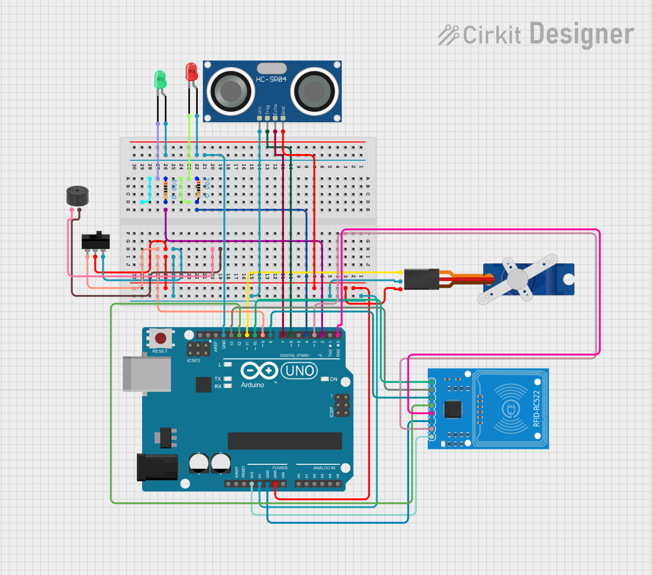
Circuit Documentation
Summary
This circuit is designed to control a toll gate system using an Arduino UNO. The system includes an RFID reader for vehicle identification, an ultrasonic sensor for vehicle detection, LEDs for status indication, a buzzer for alerts, a servo motor to control the gate, and a toggle switch for manual override. The Arduino UNO serves as the central controller, interfacing with all the components and executing the control logic.
Component List
LED: Two Pin (red)
- Pins: cathode, anode
- Description: Red LED for status indication.
- Purpose: Indicates unauthorized access.
LED: Two Pin (green)
- Pins: cathode, anode
- Description: Green LED for status indication.
- Purpose: Indicates authorized access.
Buzzer
- Pins: PIN, GND
- Description: Buzzer for alerting.
- Purpose: Alerts on unauthorized access.
Tower Pro SG90 Servo
- Pins: Signal, +5V, GND
- Description: Servo motor for gate control.
- Purpose: Opens and closes the gate.
HC-SR04 Ultrasonic Sensor
- Pins: VCC, TRIG, ECHO, GND
- Description: Ultrasonic sensor for vehicle detection.
- Purpose: Detects the presence of a vehicle.
RFID-RC522
- Pins: SDA, SCK, MOSI, MISO, IRQ, GND, RST, 3.3V
- Description: RFID reader for vehicle identification.
- Purpose: Reads RFID tags for vehicle identification.
Toggle Switch
- Pins: L1, COM, L2
- Description: Toggle switch for manual override.
- Purpose: Allows manual control of the gate.
Arduino UNO
- Pins: UNUSED, IOREF, Reset, 3.3V, 5V, GND, Vin, A0, A1, A2, A3, A4, A5, SCL, SDA, AREF, D13, D12, D11, D10, D9, D8, D7, D6, D5, D4, D3, D2, D1, D0
- Description: Microcontroller board.
- Purpose: Central controller for the circuit.
Resistor (200 Ohms)
- Pins: pin1, pin2
- Description: Resistor for current limiting.
- Purpose: Limits current to LEDs.
Wiring Details
LED: Two Pin (red)
- cathode: Not connected
- anode: Connected to GND of Arduino UNO
LED: Two Pin (green)
- cathode: Not connected
- anode: Connected to GND of Arduino UNO
Buzzer
- PIN: Not connected
- GND: Not connected
Tower Pro SG90 Servo
- Signal: Connected to D11 of Arduino UNO
- +5V: Connected to 5V of Arduino UNO
- GND: Connected to GND of Arduino UNO
HC-SR04 Ultrasonic Sensor
- VCC: Connected to 5V of Arduino UNO
- TRIG: Connected to D6 of Arduino UNO
- ECHO: Connected to D7 of Arduino UNO
- GND: Connected to GND of Arduino UNO
RFID-RC522
- SDA: Connected to D10 of Arduino UNO
- SCK: Connected to D13 of Arduino UNO
- MOSI: Connected to D8 of Arduino UNO
- MISO: Connected to D12 of Arduino UNO
- IRQ: Connected to D0 of Arduino UNO
- GND: Connected to GND of Arduino UNO
- RST: Connected to D3 of Arduino UNO
- 3.3V: Connected to 3.3V of Arduino UNO
Toggle Switch
- L1: Connected to D9 of Arduino UNO
- COM: Connected to GND of Arduino UNO
- L2: Connected to 5V of Arduino UNO
Arduino UNO
- D2: Connected to pin2 of Resistor (200 Ohms)
- D4: Connected to pin2 of Resistor (200 Ohms)
- D6: Connected to TRIG of HC-SR04 Ultrasonic Sensor
- D7: Connected to ECHO of HC-SR04 Ultrasonic Sensor
- D8: Connected to MOSI of RFID-RC522
- D9: Connected to L1 of Toggle Switch
- D10: Connected to SDA of RFID-RC522
- D11: Connected to Signal of Tower Pro SG90 Servo
- D12: Connected to MISO of RFID-RC522
- D13: Connected to SCK of RFID-RC522
- 3.3V: Connected to 3.3V of RFID-RC522
- 5V: Connected to +5V of Tower Pro SG90 Servo, VCC of HC-SR04 Ultrasonic Sensor, and L2 of Toggle Switch
- GND: Connected to GND of Tower Pro SG90 Servo, GND of HC-SR04 Ultrasonic Sensor, GND of RFID-RC522, COM of Toggle Switch, anode of LED: Two Pin (red), and anode of LED: Two Pin (green)
Resistor (200 Ohms)
- pin1: Connected to pin2 of the same resistor
- pin2: Connected to D2 of Arduino UNO
Resistor (200 Ohms)
- pin1: Connected to pin2 of the same resistor
- pin2: Connected to D4 of Arduino UNO
Code Documentation
#include <Servo.h>
#include <SPI.h>
#include <MFRC522.h>

#define TRIG_PIN 6
#define ECHO_PIN 7
#define SERVO_PIN 11
#define RED_LED_PIN 2
#define GREEN_LED_PIN 4
#define SWITCH_PIN 9
#define BUZZER_PIN 8
#define RST_PIN 3
#define SDA_PIN 10

Servo gateServo;
MFRC522 rfid(SDA_PIN, RST_PIN);

void setup() {
  Serial.begin(9600);
  SPI.begin();
  rfid.PCD_Init();
  pinMode(TRIG_PIN, OUTPUT);
  pinMode(ECHO_PIN, INPUT);
  pinMode(RED_LED_PIN, OUTPUT);
  pinMode(GREEN_LED_PIN, OUTPUT);
  pinMode(SWITCH_PIN, INPUT);
  pinMode(BUZZER_PIN, OUTPUT);
  gateServo.attach(SERVO_PIN);
  gateServo.write(0); // Gate closed
}

void loop() {
  long duration, distance;
  digitalWrite(TRIG_PIN, LOW);
  delayMicroseconds(2);
  digitalWrite(TRIG_PIN, HIGH);
  delayMicroseconds(10);
  digitalWrite(TRIG_PIN, LOW);
  duration = pulseIn(ECHO_PIN, HIGH);
  distance = (duration / 2) / 29.1;

  if (distance < 10) { // Vehicle detected
    if (rfid.PICC_IsNewCardPresent() && rfid.PICC_ReadCardSerial()) {
      Serial.println("RFID tag detected");
      digitalWrite(GREEN_LED_PIN, HIGH);
      digitalWrite(RED_LED_PIN, LOW);
      gateServo.write(90); // Open gate
      delay(5000); // Keep gate open for 5 seconds
      gateServo.write(0); // Close gate
      digitalWrite(GREEN_LED_PIN, LOW);
    } else {
      digitalWrite(RED_LED_PIN, HIGH);
      digitalWrite(GREEN_LED_PIN, LOW);
      digitalWrite(BUZZER_PIN, HIGH);
      delay(1000);
      digitalWrite(BUZZER_PIN, LOW);
    }
  } else {
    digitalWrite(RED_LED_PIN, LOW);
    digitalWrite(GREEN_LED_PIN, LOW);
  }
  delay(100);
}
This code initializes the components and sets up the pins. In the loop function, it continuously checks for the presence of a vehicle using the ultrasonic sensor. If a vehicle is detected, it checks for an RFID tag. If an authorized RFID tag is detected, it opens the gate and turns on the green LED. If no RFID tag is detected, it turns on the red LED and activates the buzzer. The gate remains open for 5 seconds before closing.