
Arduino UNO Air Purification System with MQ-135 and ENS160 Sensors
View and Edit Project In Cirkit Designer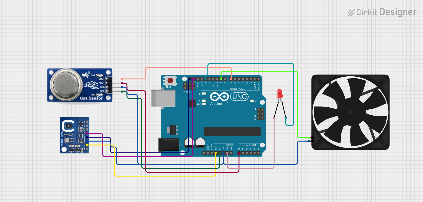
Air Purification System Documentation
Summary
This document provides a detailed overview of an air purification system designed using an Arduino UNO microcontroller. The system monitors air quality using the MQ-135 and ENS160+AHT21 sensors. If poor air quality is detected, it activates an LED and turns on a fan to purify the air.
Component List
Arduino UNO
- Description: Microcontroller board based on the ATmega328P.
- Pins: UNUSED, IOREF, Reset, 3.3V, 5V, GND, Vin, A0, A1, A2, A3, A4, A5, SCL, SDA, AREF, D13, D12, D11, D10, D9, D8, D7, D6, D5, D4, D3, D2, D1, D0
ENS160+AHT21
- Description: Air quality sensor module.
- Pins: VIN, 3V3, GND, SCL, SDA, ADD, CS, INT
Fan
- Description: DC fan for air circulation.
- Pins: GND, 5V
MQ 135
- Description: Air quality sensor for detecting gases.
- Pins: D OUT, A OUT, GND, VCC
LED: Two Pin (red)
- Description: Red LED indicator.
- Pins: cathode, anode
Wiring Details
Arduino UNO
- 3.3V connected to ENS160+AHT21 3V3
- 5V connected to MQ 135 VCC
- GND connected to ENS160+AHT21 GND, MQ 135 GND, Fan GND, LED cathode
- A0 connected to MQ 135 A OUT
- SCL connected to ENS160+AHT21 SCL
- SDA connected to ENS160+AHT21 SDA
- D13 connected to LED anode
- D9 connected to Fan 5V
- D7 connected to MQ 135 D OUT
ENS160+AHT21
- 3V3 connected to Arduino UNO 3.3V
- GND connected to Arduino UNO GND
- SCL connected to Arduino UNO SCL
- SDA connected to Arduino UNO SDA
Fan
- GND connected to Arduino UNO GND
- 5V connected to Arduino UNO D9
MQ 135
- VCC connected to Arduino UNO 5V
- GND connected to Arduino UNO GND
- A OUT connected to Arduino UNO A0
- D OUT connected to Arduino UNO D7
LED: Two Pin (red)
- cathode connected to Arduino UNO GND
- anode connected to Arduino UNO D13
Code Documentation
/*
 * Air Purification System
 * This Arduino sketch monitors the air quality using the MQ-135 sensor and the
 * ENS160+AHT21 sensor. If poor air quality is detected, it activates an LED and
 * turns on a fan to purify the air.
 */

#include <Wire.h>
#include <ScioSense_ENS160.h>
//#include <SparkFun_ENS160.h>
//#include <ENS160.h>

#define MQ135_AOUT_PIN A0
#define MQ135_DOUT_PIN 7
#define FAN_PIN 9
#define LED_PIN 13

ScioSense_ENS160 ens160(ENS160_I2CADDR_1);
//ENS160 ens160;

void setup() {
  // Initialize serial communication
  Wire.begin();
  Serial.begin(9600);

  // Initialize the ENS160 sensor
  if (!ens160.begin()) {
    Serial.println("Failed to find ENS160 sensor!");
    while (1) {
      digitalWrite(LED_PIN, HIGH);
      delay(500);
      digitalWrite(LED_PIN, LOW);
      delay(500);
    }
  }

  // Initialize pins
  pinMode(MQ135_DOUT_PIN, INPUT);
  pinMode(FAN_PIN, OUTPUT);
  pinMode(LED_PIN, OUTPUT);

  // Turn off fan and LED initially
  analogWrite(FAN_PIN, 0);
  digitalWrite(LED_PIN, LOW);
}

void loop() {
  // Read air quality from MQ-135 sensor
  int airQualityAnalog = analogRead(MQ135_AOUT_PIN);
  int airQualityDigital = digitalRead(MQ135_DOUT_PIN);

  // Read air quality from ENS160 sensor
  ens160.measure(true);
  ens160.measureRaw(true);
  int ens160AQI = ens160.getAQI();

  // Print sensor values to serial monitor
  Serial.print("Analog: "); Serial.print(airQualityAnalog);
  Serial.print(", Digital: "); Serial.print(airQualityDigital);
  Serial.print(", AQI: "); Serial.println(ens160AQI);

  // Check air quality and activate fan and LED if poor
  if (airQualityAnalog > 400 || airQualityDigital == HIGH || ens160AQI > 75) {
    analogWrite(FAN_PIN, 255);
    digitalWrite(LED_PIN, HIGH);
  } else {
    analogWrite(FAN_PIN, 0);
    digitalWrite(LED_PIN, LOW);
  }

  // Delay before next reading
  delay(2000);
}
This code initializes the sensors and reads air quality data from both the MQ-135 and ENS160+AHT21 sensors. If poor air quality is detected, it activates the fan and LED to indicate and address the issue. The sensor values are also printed to the serial monitor for debugging and monitoring purposes.