
Wi-Fi Controlled 4-Channel Relay System with Arduino and ESP8266
View and Edit Project In Cirkit Designer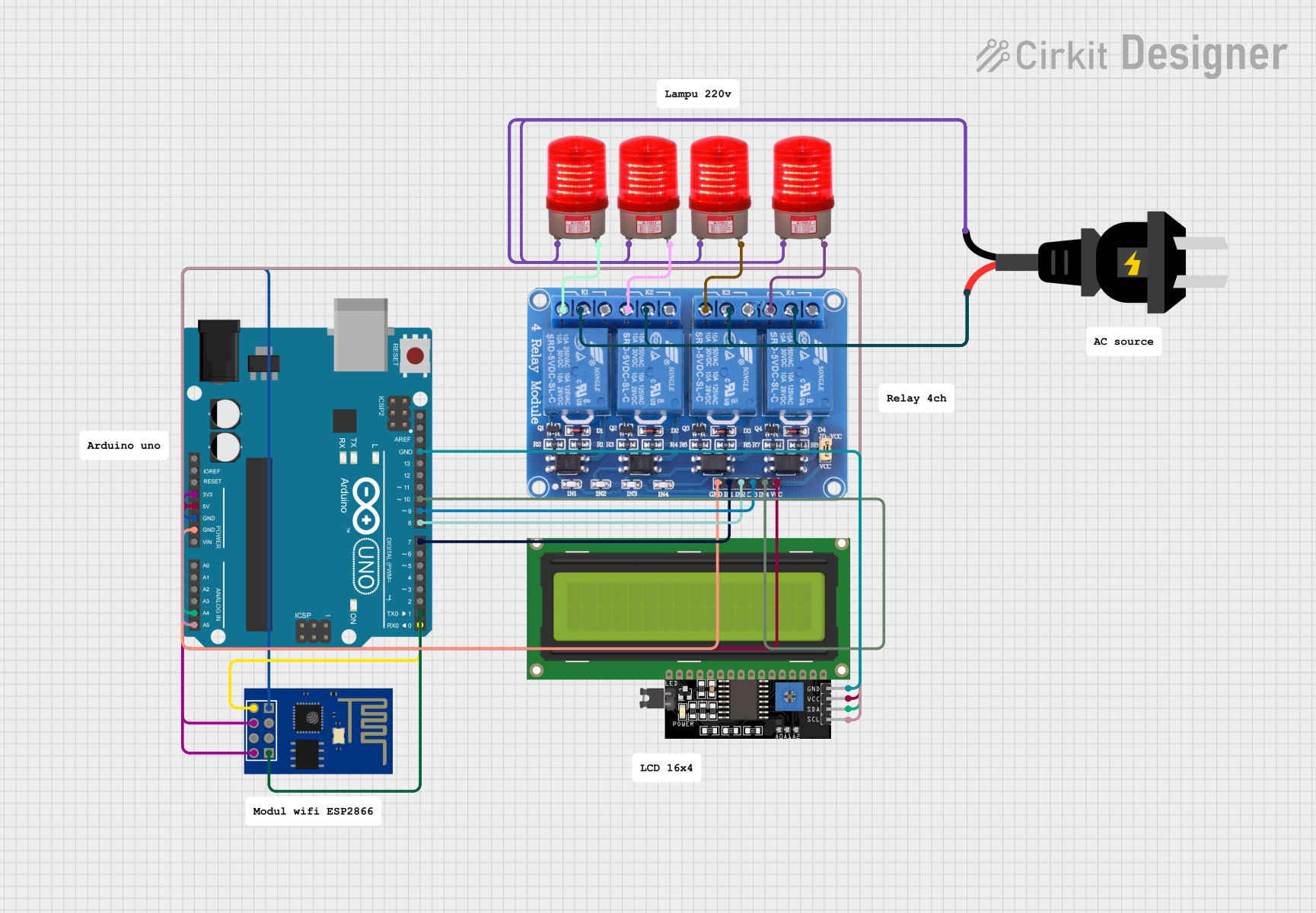
Circuit Documentation
Summary
This circuit is a Wi-Fi controlled 4-channel relay system using an Arduino UNO and an ESP8266 ESP-01 WiFi module. The relays can be controlled via a web interface served by the ESP8266. The Arduino UNO handles the relay control and communicates with the ESP8266 via serial communication. An LCD display is used to show the status of each relay. The relays are connected to various 220V AC red lights.
Component List
ESP8266 ESP-01 WiFi Module
- Description: WiFi module for wireless communication.
- Pins: TXD, CH_PD, RST, VCC, GND, GPIO_2, GPIO_0, RXD
Relay 4 Channel 5v
- Description: 4-channel relay module for controlling high voltage devices.
- Pins: GND, IN1, IN2, IN3, IN4, VCC, COM1, COM2, COM3, COM4, NO1, NO2, NO3, NO4, NC1, NC2, NC3, NC4
Arduino UNO
- Description: Microcontroller board based on the ATmega328P.
- Pins: UNUSED, IOREF, Reset, 3.3V, 5V, GND, Vin, A0, A1, A2, A3, A4, A5, SCL, SDA, AREF, D13, D12, D11, D10, D9, D8, D7, D6, D5, D4, D3, D2, D1, D0
LCD Display 16x4 I2C
- Description: 16x4 character LCD display with I2C interface.
- Pins: SCL, SDA, VCC, GND
Red Light 220VAC
- Description: 220V AC red indicator light.
- Pins: -, +
AC Source
- Description: AC power source.
- Pins: -, +
Wiring Details
ESP8266 ESP-01 WiFi Module
- TXD connected to D0 of Arduino UNO
- CH_PD connected to 3.3V of Arduino UNO
- VCC connected to 3.3V of Arduino UNO
- GND connected to GND of Arduino UNO
- RXD connected to D1 of Arduino UNO
Relay 4 Channel 5v
- GND connected to GND of Arduino UNO
- IN1 connected to D7 of Arduino UNO
- IN2 connected to D8 of Arduino UNO
- IN3 connected to D9 of Arduino UNO
- IN4 connected to D10 of Arduino UNO
- VCC connected to 5V of Arduino UNO
- COM1, COM2, COM3, COM4 connected to - of AC Source
- NC1 connected to - of Red Light 220VAC
- NC2 connected to - of Red Light 220VAC
- NC3 connected to - of Red Light 220VAC
- NC4 connected to - of Red Light 220VAC
Arduino UNO
- D0 connected to TXD of ESP8266 ESP-01 WiFi Module
- D1 connected to RXD of ESP8266 ESP-01 WiFi Module
- 3.3V connected to CH_PD and VCC of ESP8266 ESP-01 WiFi Module
- GND connected to GND of ESP8266 ESP-01 WiFi Module and Relay 4 Channel 5v
- D7 connected to IN1 of Relay 4 Channel 5v
- D8 connected to IN2 of Relay 4 Channel 5v
- D9 connected to IN3 of Relay 4 Channel 5v
- D10 connected to IN4 of Relay 4 Channel 5v
- 5V connected to VCC of Relay 4 Channel 5v and LCD Display 16x4 I2C
- A4 connected to SDA of LCD Display 16x4 I2C
- A5 connected to SCL of LCD Display 16x4 I2C
LCD Display 16x4 I2C
- VCC connected to 5V of Arduino UNO
- SDA connected to A4 of Arduino UNO
- SCL connected to A5 of Arduino UNO
- GND connected to GND of Arduino UNO
Red Light 220VAC
- - connected to NC1, NC2, NC3, NC4 of Relay 4 Channel 5v
- + connected to + of AC Source
AC Source
- - connected to COM1, COM2, COM3, COM4 of Relay 4 Channel 5v
- + connected to + of Red Light 220VAC
Code Documentation
/*
 * Wi-Fi Controlled 4-Channel Relay with Arduino and ESP8266
 * This code allows control of 4 relays via Wi-Fi using the ESP8266 module.
 * The relays can be controlled through a web interface served by the ESP8266.
 * The relays are connected to digital pins D7, D8, D9, and D10 of the Arduino.
 * The ESP8266 communicates with the Arduino via serial communication.
 * The LCD display shows the status of each relay.
 */

#include <Wire.h>
#include <LiquidCrystal_I2C.h>

LiquidCrystal_I2C lcd(0x27, 16, 4);

const int relayPins[4] = {7, 8, 9, 10};

void setup() {
  Serial.begin(115200); // Initialize serial communication with ESP8266
  for (int i = 0; i < 4; i++) {
    pinMode(relayPins[i], OUTPUT);
    digitalWrite(relayPins[i], HIGH); // Turn off all relays initially
  }
  lcd.begin();
  lcd.backlight();
  lcd.setCursor(0, 0);
  lcd.print("Relay Status:");
  updateLCD();
}

void loop() {
  if (Serial.available()) {
    char command = Serial.read();
    int relayIndex = command - '1';
    if (relayIndex >= 0 && relayIndex < 4) {
      digitalWrite(relayPins[relayIndex], !digitalRead(relayPins[relayIndex]));
      updateLCD();
    }
  }
}

void updateLCD() {
  for (int i = 0; i < 4; i++) {
    lcd.setCursor(0, i + 1);
    lcd.print("Relay ");
    lcd.print(i + 1);
    lcd.print(": ");
    lcd.print(digitalRead(relayPins[i]) == LOW ? "ON " : "OFF");
  }
}
This code initializes the relays and the LCD display. It reads commands from the ESP8266 via serial communication to toggle the relays and updates the LCD display to show the status of each relay.