
ESP32-S3 and AD8232 Heart Rate Monitor with Electrode Detection
View and Edit Project In Cirkit Designer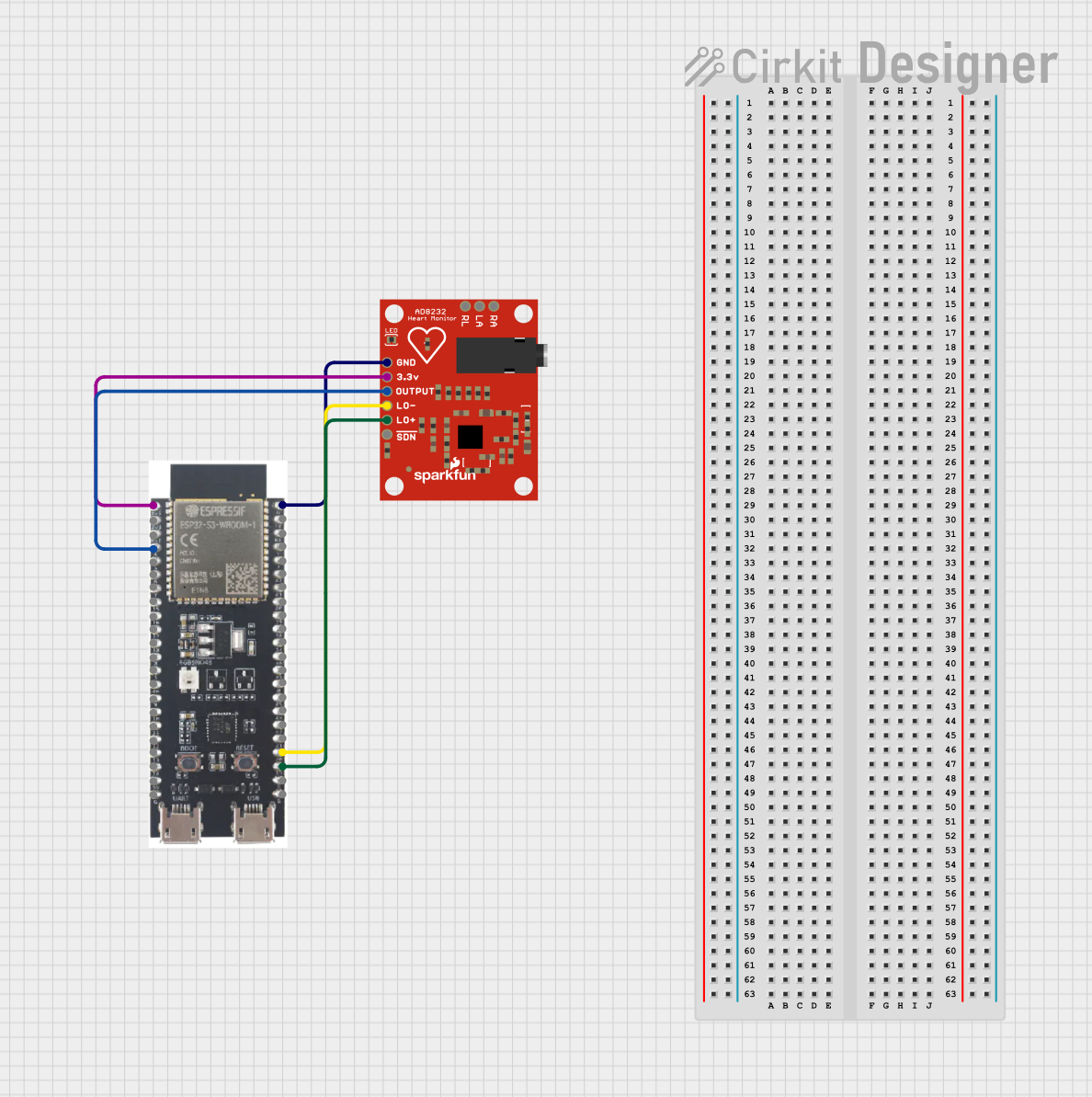
Circuit Documentation
Summary
This circuit is designed to monitor heart rate using an AD8232 Heart Rate Monitor sensor and an ESP32-S3 microcontroller. The AD8232 sensor captures the heart rate signal and sends it to the ESP32-S3, which processes the signal and outputs the data to a serial monitor. The circuit also monitors the electrode status to ensure proper attachment.
Component List
AD8232 Heart Rate Monitor
- Description: A sensor module used to measure the electrical activity of the heart.
- Pins: GND, 3.3v, OUTPUT, LO-, LO+, SDN, RA, LA, RL
ESP32-S3
- Description: A powerful microcontroller with built-in Wi-Fi and Bluetooth capabilities.
- Pins: 3v3, EN, GPIO4, GPIO5, GPIO6, GPIO7, GPIO15, GPIO16, GPIO17, GPIO18, GPIO8, GPIO46, GPIO9, GPIO10, GPIO11, GPIO12, GPIO13, GPIO14, 5V, GND, GPIO43, GPIO44, GPIO1, GPIO2, GPIO42, GPIO41, GPIO40, GPIO39, GPIO38, GPIO37, GPIO36, GPIO35, GPIO0, GPIO45, GPIO48, GPIO47, GPIO21, GPIO20, GPIO19
Wiring Details
AD8232 Heart Rate Monitor
- GND connected to ESP32-S3 GND
- 3.3v connected to ESP32-S3 3v3
- OUTPUT connected to ESP32-S3 GPIO4
- LO- connected to ESP32-S3 GPIO20
- LO+ connected to ESP32-S3 GPIO19
ESP32-S3
- GND connected to AD8232 Heart Rate Monitor GND
- 3v3 connected to AD8232 Heart Rate Monitor 3.3v
- GPIO4 connected to AD8232 Heart Rate Monitor OUTPUT
- GPIO20 connected to AD8232 Heart Rate Monitor LO-
- GPIO19 connected to AD8232 Heart Rate Monitor LO+
Code Documentation
/*
 * Electrocardiograph (ECG) using ESP32-S3 and AD8232 sensor
 * This code reads the heart rate signal from the AD8232 sensor and prints
 * the values to the Serial Monitor. It also monitors the LO+ and LO- pins
 * to detect if the electrodes are properly attached.
 */

// Pin definitions
const int ecgPin = 4; // ECG signal from AD8232 OUTPUT pin
const int loPlusPin = 19; // LO+ pin from AD8232
const int loMinusPin = 20; // LO- pin from AD8232

void setup() {
  // Initialize serial communication
  Serial.begin(115200);

  // Configure pin modes
  pinMode(ecgPin, INPUT);
  pinMode(loPlusPin, INPUT);
  pinMode(loMinusPin, INPUT);
}

void loop() {
  // Read ECG signal
  int ecgValue = analogRead(ecgPin);

  // Read electrode status
  int loPlusStatus = digitalRead(loPlusPin);
  int loMinusStatus = digitalRead(loMinusPin);

  // Print ECG value
  Serial.print("ECG Value: ");
  Serial.println(ecgValue);

  // Check electrode status
  if (loPlusStatus == HIGH || loMinusStatus == HIGH) {
    Serial.println("Electrodes not properly attached!");
  }

  // Delay for stability
  delay(10);
}
This code initializes the necessary pins on the ESP32-S3, reads the ECG signal from the AD8232 sensor, and prints the values to the Serial Monitor. It also checks the status of the LO+ and LO- pins to ensure the electrodes are properly attached.