Arduino UNO Controlled Color Sorting Machine with LCD Feedback and Servo Mechanism
Circuit Documentation
Summary
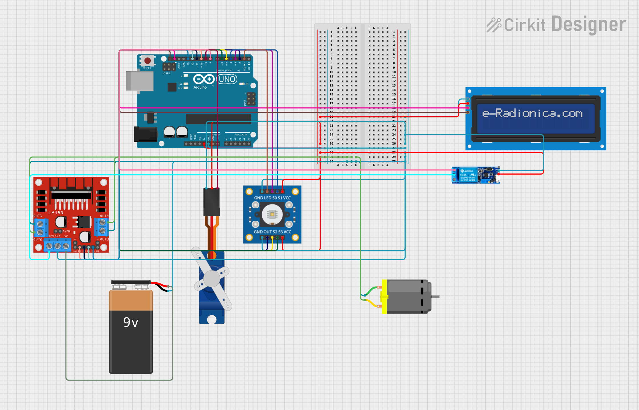
This circuit is designed to interface an Arduino UNO with various peripherals including an LCD screen, a servo motor, a DC motor via an L298N motor driver, a TCS3200 color sensor, and a relay module. The Arduino UNO serves as the central microcontroller unit, controlling the inputs and outputs to the other components. The LCD screen displays information, the servo motor adjusts positions, the DC motor provides motion, the TCS3200 color sensor detects color, and the relay module switches power to the motor driver. The circuit is powered by a 9V battery.
Component List
Arduino UNO
A microcontroller board based on the ATmega328P. It has 14 digital input/output pins, 6 analog inputs, a 16 MHz quartz crystal, a USB connection, a power jack, an ICSP header, and a reset button.
TCS3200 Color Sensor
A color sensor module that can detect and measure a wide range of colors. It includes output pins and control pins for setting the frequency scaling.
Tower Pro SG90 Servo
A small and lightweight servo motor capable of precise control. It can be used for various applications like steering mechanisms in RC vehicles or robotic arms.
DC Motor
A standard DC motor used for providing rotational motion.
L298N DC Motor Driver
A motor driver module capable of driving two DC motors. It has pins for motor outputs, power supply, and control inputs.
Relay Module 5V-30V
A relay module that can switch high voltages and currents using a low voltage signal from a microcontroller.
9V Battery
A standard 9V battery used as the power source for the circuit.
LCD Screen 16x2 I2C
An alphanumeric liquid crystal display capable of displaying 16 characters per line across 2 lines. It uses the I2C communication protocol.
Wiring Details
Arduino UNO
5Vto LCD screen, servo motor, relay module, TCS3200 color sensorGNDto LCD screen, relay module, servo motor, motor driver, TCS3200 color sensor, 9V batterySCLto LCD screenSDAto LCD screenD13to motor driverIN4D12to motor driverIN3D11to motor driverIN2D10to motor driverIN1D9to servo motorSignalD8to relay modulenormally openD6to TCS3200S3D5to TCS3200S2D4to TCS3200S1D3to TCS3200S0D2to TCS3200OUTD1to TCS3200LED
TCS3200 Color Sensor
VCCto 5V power supplyGNDto groundOUTto Arduino UNOD2S0to Arduino UNOD3S1to Arduino UNOD4S2to Arduino UNOD5S3to Arduino UNOD6LEDto Arduino UNOD1
Tower Pro SG90 Servo
Signalto Arduino UNOD9+5Vto 5V power supplyGNDto ground
DC Motor
pin 1to motor driverOUT1andOUT3pin 2to motor driverOUT2andOUT4
L298N DC Motor Driver
OUT1,OUT3to DC motorpin 1OUT2,OUT4to DC motorpin 2GNDto ground12Vto relay modulecommon contact5Vto 9V battery+IN1to Arduino UNOD10IN2to Arduino UNOD11IN3to Arduino UNOD12IN4to Arduino UNOD13
Relay Module 5V-30V
common contactto motor driver12Vnormally opento Arduino UNOD8V+to 5V power supplyV-to ground
9V Battery
+to motor driver5V-to ground
LCD Screen 16x2 I2C
SCLto Arduino UNOSCLSDAto Arduino UNOSDAVCCto 5V power supplyGNDto ground
Documented Code
#include <Wire.h>
#include <LiquidCrystal_I2C.h>
#include <Servo.h>

// Initialize the I2C LCD
LiquidCrystal_I2C lcd(0x27, 16, 2); // Set the LCD I2C address

// Initialize the servo
Servo myservo;

// Define pin connections
const int tcs3200OutPin = 2; // Output from the TCS3200
const int tcs3200S0Pin = 3; // S0 pin of the TCS3200
const int tcs3200S1Pin = 4; // S1 pin of the TCS3200
const int tcs3200S2Pin = 5; // S2 pin of the TCS3200
const int tcs3200S3Pin = 6; // S3 pin of the TCS3200
const int servoPin = 9; // Control pin for servo motor
const int motorDriverIn1 = 10; // IN1 on the L298N
const int motorDriverIn2 = 11; // IN2 on the L298N
const int motorDriverIn3 = 12; // IN3 on the L298N
const int motorDriverIn4 = 13; // IN4 on the L298N
const int relayPin = 8; // Relay control pin

void setup() {
  // Set up the LCD
  lcd.init();
  lcd.backlight();
  lcd.print("Hello, World!");

  // Set up the servo
  myservo.attach(servoPin);
  myservo.write(90); // Set servo to mid-point

  // Set up the TCS3200 pins
  pinMode(tcs3200OutPin, INPUT);
  pinMode(tcs3200S0Pin, OUTPUT);
  pinMode(tcs3200S1Pin, OUTPUT);
  pinMode(tcs3200S2Pin, OUTPUT);
  pinMode(tcs3200S3Pin, OUTPUT);

  // Set frequency scaling to 20%
  digitalWrite(tcs3200S0Pin, HIGH);
  digitalWrite(tcs3200S1Pin, LOW);

  // Set up the motor driver pins
  pinMode(motorDriverIn1, OUTPUT);
  pinMode(motorDriverIn2, OUTPUT);
  pinMode(motorDriverIn3, OUTPUT);
  pinMode(motorDriverIn4, OUTPUT);

  // Set up the relay pin
  pinMode(relayPin, OUTPUT);
  digitalWrite(relayPin, LOW); // Turn off the relay

  // Set initial motor speed and direction
  digitalWrite(motorDriverIn1, LOW);
  digitalWrite(motorDriverIn2, HIGH);
  digitalWrite(motorDriverIn3, LOW);
  digitalWrite(motorDriverIn4, HIGH);
}

void loop() {
  // This is where you would add the code to interact with the components.
  // For example, you could read from the TCS3200, move the servo, display
  // something on the LCD, control the motor, or toggle the relay.
}
This code initializes and controls the various components connected to the Arduino UNO. It sets up the LCD screen, servo motor, TCS3200 color sensor, motor driver, and relay module. The setup() function configures the pins and sets initial states, while the loop() function is left empty for the user to fill with their specific application logic.