Cirkit Designer
Your all-in-one circuit design IDE
Home /
Project Documentation
Arduino UNO Bluetooth-Controlled Smart Light with Relay
Circuit Documentation
Summary
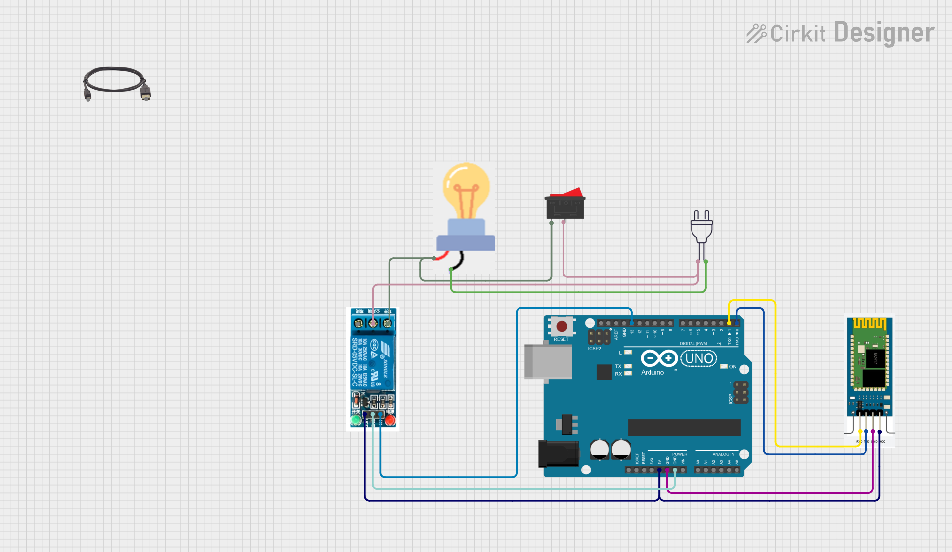
This circuit involves an Arduino UNO microcontroller, an HC-06 Bluetooth module, a 5V relay, a bulb, a rocker switch, and a power source. The Arduino UNO controls the relay based on commands received via the HC-06 Bluetooth module. The relay, in turn, controls the bulb connected to a 220V power source. The rocker switch is used to manually control the bulb.
Component List
Arduino UNO
- Description: A microcontroller board based on the ATmega328P.
- Pins: UNUSED, IOREF, Reset, 3.3V, 5V, GND, Vin, A0, A1, A2, A3, A4, A5, SCL, SDA, AREF, D13, D12, D11, D10, D9, D8, D7, D6, D5, D4, D3, D2, D1, D0
HC-06
- Description: A Bluetooth module used for wireless communication.
- Pins: RXD, TXD, GND, VCC
Bulb
- Description: An electrical bulb.
- Pins: GND, power
Rocker Switch
- Description: A switch used to manually control the bulb.
- Pins: 1, 2
5V Relay
- Description: A relay module used to control high voltage devices.
- Pins: Normally Open, Common terminal, Normally Closed, In, GND, VCC
Power 220V
- Description: A 220V power source.
- Pins: hot wire, neutral wire
Type-B to USB
- Description: A cable used to connect the Arduino UNO to a computer.
- Pins: Type-B, USB
Wiring Details
Arduino UNO
- 5V is connected to VCC of HC-06 and VCC of 5V relay.
- GND is connected to GND of HC-06 and GND of 5V relay.
- D13 is connected to In of 5V relay.
- D1 is connected to RXD of HC-06.
- D0 is connected to TXD of HC-06.
HC-06
- VCC is connected to 5V of Arduino UNO and VCC of 5V relay.
- GND is connected to GND of Arduino UNO.
- RXD is connected to D1 of Arduino UNO.
- TXD is connected to D0 of Arduino UNO.
Bulb
- GND is connected to neutral wire of power 220V.
- power is connected to 1 of Rocker Switch and Normally Open of 5V relay.
Rocker Switch
- 1 is connected to power of Bulb and Normally Open of 5V relay.
- 2 is connected to Common terminal of 5V relay and hot wire of power 220V.
5V Relay
- VCC is connected to 5V of Arduino UNO and VCC of HC-06.
- GND is connected to GND of Arduino UNO.
- In is connected to D13 of Arduino UNO.
- Normally Open is connected to 1 of Rocker Switch and power of Bulb.
- Common terminal is connected to 2 of Rocker Switch and hot wire of power 220V.
Power 220V
- hot wire is connected to Common terminal of 5V relay and 2 of Rocker Switch.
- neutral wire is connected to GND of Bulb.
Code Documentation
Arduino UNO Code
char val;

void setup() {
    pinMode(13, OUTPUT);
    Serial.begin(9600);
    digitalWrite(13, HIGH);
}

void loop() {
    if (Serial.available()) {
        val = Serial.read();
        Serial.println(val);
    }
    if (val == '1') {
        digitalWrite(13, LOW);
    } else if (val == '2') {
        digitalWrite(13, HIGH);
    }
    delay(100);
}
Explanation:
- setup(): Initializes pin 13 as an output, starts serial communication at 9600 baud, and sets pin 13 to HIGH.
- loop(): Continuously checks for available serial data. If data is available, it reads the data and prints it to the serial monitor. If the received data is '1', it sets pin 13 to LOW, turning off the relay. If the received data is '2', it sets pin 13 to HIGH, turning on the relay. The loop includes a 100ms delay to prevent rapid toggling.